Hi,
The theme of this amp is hi loop gain so that distortion
can be so low that the main problem is choosing parts
and layout.
What motivated me was that maybe the ear really has a
wider dynamic range than we can believe. Therefore why
not push distortion as low as possible?
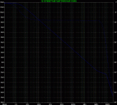
The 0db point is around 1.8Mhz and OL gain is around
118db. It looks like things should be stable (see attached
loop gain diagram) in theory. Don't know about practice
which is one of the main reasons for me posting this.
I'm no super expert just a hobbyist, and I asked Bob C.,
and Andy C. for early revue on this, which they both
graciously provided.
I'll post more stuff as I get it formatted and uploaded.
I may be a little slow due to my workload.
So far it has just been simulated in LTSpice. I know Spice
can only go so far.
Mike
The theme of this amp is hi loop gain so that distortion
can be so low that the main problem is choosing parts
and layout.
What motivated me was that maybe the ear really has a
wider dynamic range than we can believe. Therefore why
not push distortion as low as possible?
The 0db point is around 1.8Mhz and OL gain is around
118db. It looks like things should be stable (see attached
loop gain diagram) in theory. Don't know about practice
which is one of the main reasons for me posting this.
I'm no super expert just a hobbyist, and I asked Bob C.,
and Andy C. for early revue on this, which they both
graciously provided.
I'll post more stuff as I get it formatted and uploaded.
I may be a little slow due to my workload.
So far it has just been simulated in LTSpice. I know Spice
can only go so far.
Mike
Attachments
Nice design with advanced techniques used!
I see you are using nested differential feedback instead of typical miller. This brings great THD reduction but tends to big stability issues on different loads.
Same goes to input stage which is casoded sziklai pairs.
A third potential source of instability is mosfets predrivers. Usual way to make them more stable is to add a gate resistor, but with NDFL you may need some fancier way to not lose too much speed.
My advice is to play a little bit with snubbers and ferrite beads and take care of layout.
I think you should definitely build a prototype, if real life results bring results even close to simulation results you may feel proud of yourself.
This may be a tough experience, but definitely worth it!
Regards,
Adam
P.S. What's the bias?
P.S. What's the bias? [/B]
Its set at a little over 200ma thru each output transistor.
So class A at low signal levels, class B at higher.
Thanks for the comments regarding NDFL. I was cautioned
by both Bob and Andy about this. Both mentioned using TMC.
In Sim, I didn't seem to run into any problems even with
capacitve loads up to 4uF // 1 ohm.
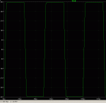
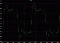
Attached is a ~45v 20Khz square into 4uF // 1ohm.
I saw more problems using a bipolar output driver like the
MJE15034. This was harder to control. Using the ECX10N16
in this position was easier. Maybe this is a modeling issue?
Mike
Attachments
Keep in mind that mosfets in reality are only slightly faster than bipolars.
Your slew rate is so-so, expect stability issues as if you ued all bipolar amp, such a simulated waveform on capacitive load usually means wild oscillation in reality.
Don't get me wrong, some schematics are just easier to put into real-life working amplifier with no strange phenomena expected, yours is not.
not really a super pair - above ~ 4KHz C1 will short out the VAS "driver" Q7 collector turning the high frequency model into a complemntary Darlington with emitter degeneration for the VAS Q8
C2 is the main Cdom in Cherry's recommended output stage enclosing position - enclosing 4 stages (Q7,8 VAS and mosfet driver + BJT outut) - certainly commonly questioned but Cherry claims this can be stablized
I'm suprized at the sim's gain and distortion performance - never would have thought CFP input diff pair was very useful
In sim the fun part would be to switch things around with simpler individual stages and/or totally idealized stages to see where the apparent performance is coming from
Lumba Ogir said:Not even Baxandall managed to make it work.

Bet Baxandall could make it work in a sim.

To bad we don't live in the Matrix......or do we?

jcx said:In sim the fun part would be to switch things around with simpler individual stages and/or totally idealized stages to see where the apparent performance is coming from
Hi,
Yes this had me wondering too, and I'd tried it in the past.
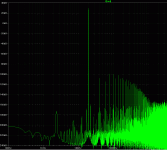
Looking at the 20Khz 45v sim you can see the
4th harmonic comes in around -99db
3rd harmonic around -114db
2nd harmonic -107db
I looked at removing or simplifying several of the mechanisms:
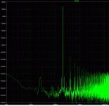
A. Simply removing the CFP, and everything else the same moves
the 3rd harmonic up to -74db.
B. Simply deleting the NPN from the super pair (don't know
what else to call it???) and going straight into the PNP (no longer
a super pair), and eliminating the small 20 ohm emitter resistor,
everything else the same moves the 2nd harmonic up to -58db.
C. Removing the NDFL cap, changing the local 2pf cap to 120pf,
so we have roughly the same 1.8Mhz 0db point, everything
else the same moves the 3rd harmonic up to -57db.
These aren't additive. Looked at removing a combination
of mechanisms.
Removing A. and C. and everything else the same moves
the 3rd harmonic up to -56db.
Removing A. and B. and everything else the same moves
the 2nd harmonic up to -56db.
Removing B. and C. and everything else the same moves
the 3rd harmonic up to -55db.
Removing A., B., and C. and everything else the same moves
the 2nd harmonic up to -55db.
So it looks like they all work in conjunction with each other.
yes sometimes Everything depends on Everything else
Mike's hi-loop gain amp circuit 12th_asc from zip above:
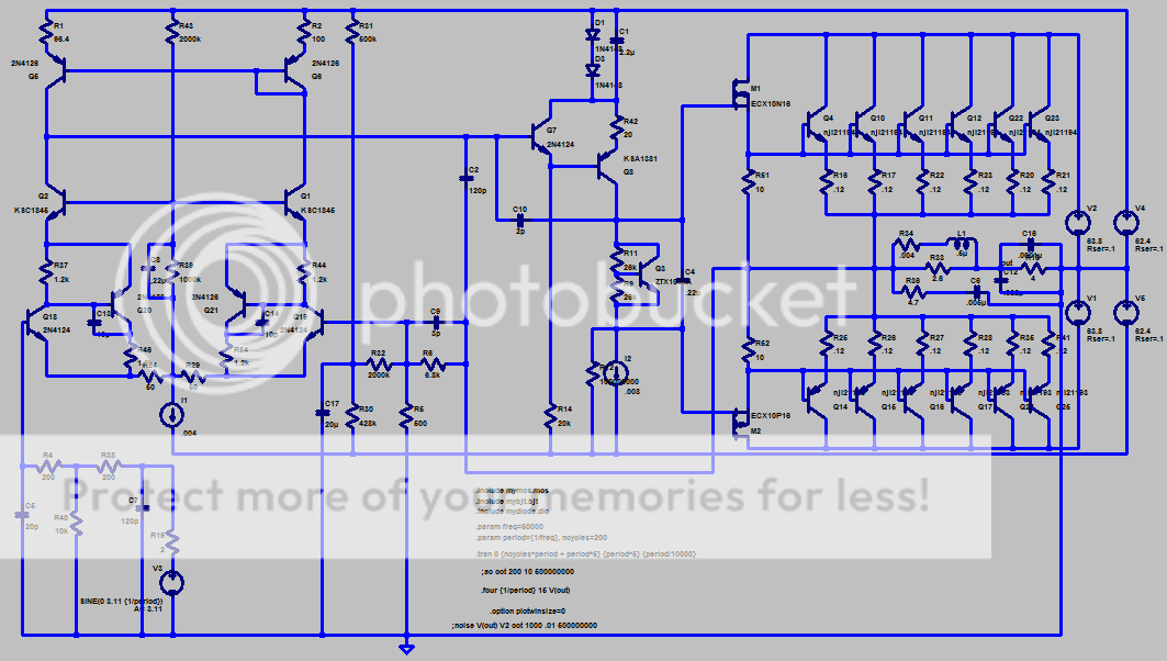
(I compacted the schematic and twisted the the input under the circuit to get ~ 1000 pixel width and keep ref designators almost readable so more people won't have to scroll too far)
ps
the fundamental null ltspice tool in mfc's zip is a little different from my 1st post of the circuit here:
http://www.diyaudio.com/forums/showthread.php?postid=1333137#post1333137
please let me know if you find bugs in the original
Mike's hi-loop gain amp circuit 12th_asc from zip above:
(I compacted the schematic and twisted the the input under the circuit to get ~ 1000 pixel width and keep ref designators almost readable so more people won't have to scroll too far)
ps
the fundamental null ltspice tool in mfc's zip is a little different from my 1st post of the circuit here:
http://www.diyaudio.com/forums/showthread.php?postid=1333137#post1333137
please let me know if you find bugs in the original
darkfenriz said:Your slew rate is so-so...
Yep, hi loop gain and low distortion, but not fast.
jcx said:the fundamental null ltspice tool in mfc's zip is a little different from my 1st post of the circuit here:
http://www.diyaudio.com/forums/showthread.php?postid=1333137#post1333137
please let me know if you find bugs in the original [/B]
Hi,
I use that fundamental null tool a lot. I find that
its results match a "full" simulation, so I use it for fast turn
around to try ideas out.
Also, thanks for your early inspiration of this work on hi-loop gain.
Mike
jcx, I use cfp in Ltp all the time, standard for me for some years, but mine with Jfet Bjt combination. This was proposed as a superior combination by JLH back in the late 70s. mfc has used the cfps in a rather different way, the resistors curb the feedback a little, a property which works well when I use cfps in a output configuration as driver to curb stability problems although I dont think it is required in the ltp nor those caps.
The vas is definetly a baxandall super pair, very high gain, mfc has it used here in an innovative way, maybe it will be stable, only a build and scope test would tell. The resitor R42 would help a great deal for stability too. I have only seen one comercial use of the baxandall super pair as a vas, in a subwoofer amp, would be interesting to know if that manufacturer was able to tame it. The super pair works excelent for current sources though, 3 transistor sources can be made with extremely high output impedance and minimal capacitance, great for PSRR.
mfc I hope you build this and let us know if you could tame that vas.
I agree, the combination of CFP JFET/bipolar is "the perfect" input stage. The same warm and musical sound as JFETs only, but with less grain, and no problematic bias currents so you don't have to use input caps.homemodder said:jcx, I use cfp in Ltp all the time, standard for me for some years, but mine with Jfet Bjt combination. This was proposed as a superior combination by JLH back in the late 70s.
- Status
- This old topic is closed. If you want to reopen this topic, contact a moderator using the "Report Post" button.
- Home
- Amplifiers
- Solid State
- hi-loop gain amp