Re: I guess I have comments...
LOL, strange conincidence indeed.
Well that is a pseudo technical explanation that may appeal to those who don’t know any better. Is your amp continuously slew rate limiting during use?
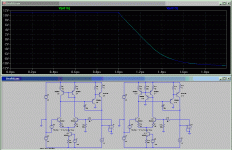
I guess I have nothing better to do, so attached below is a 100kHz squarewave simulation of two opamps, identical besides the LTP current mirror (stock Vs 3-T). The output waveforms are superimposed (green, blue traces). Please point out the “superior decay at HF”.
ostripper said:What is strange , your mention of this on the thread happened
right at the time I was testing it. And it is the mod, when applied,
that you can really HEAR.
LOL, strange conincidence indeed.
ostripper said:It just does. Perhaps it has something to do with slewing
positive vs. negetive(AKSA first mentioned it gives better decay
at HF).
Well that is a pseudo technical explanation that may appeal to those who don’t know any better. Is your amp continuously slew rate limiting during use?
I guess I have nothing better to do, so attached below is a 100kHz squarewave simulation of two opamps, identical besides the LTP current mirror (stock Vs 3-T). The output waveforms are superimposed (green, blue traces). Please point out the “superior decay at HF”.
Attachments
Re: Re: I guess I have comments...
Really, the resolution is way too low to see the difference.

Here's another exercise while you don't have much to do: show the remarkable difference between these two in THD and current sharing that my low rez sim didn't illuminate.
Go on, I dare you.

My sim, using that exact same configuration in OS's amp gave the higher THD and didn't make any difference whatsoever in the balancing of voltage and current through legs of the LTP.
G.Kleinschmidt said:
I guess I have nothing better to do, so attached below is a 100kHz squarewave simulation of two opamps, identical besides the LTP current mirror (stock Vs 3-T). The output waveforms are superimposed (green, blue traces). Please point out the “superior decay at HF”.
Really, the resolution is way too low to see the difference.
Here's another exercise while you don't have much to do: show the remarkable difference between these two in THD and current sharing that my low rez sim didn't illuminate.
Go on, I dare you.
My sim, using that exact same configuration in OS's amp gave the higher THD and didn't make any difference whatsoever in the balancing of voltage and current through legs of the LTP.
Attachments
Re: Re: Re: I guess I have comments...
If you say so.
You really don't get it, huh?
The difference to the complete amplifiers performance isn't remarkable. In fact it's next to nill and it is a complete waste of time (just from a technical POV) to attempt to examine these (insignificant IMHO, despite GEB protests) differences in simulation with a THD resolution of 0.001%
MJL21193 said:Really, the resolution is way too low to see the difference.
If you say so.
MJL21193 said:Here's another exercise while you don't have much to do: show the remarkable difference between these two in THD and current sharing that my low rez sim didn't illuminate.
Go on, I dare you.
You really don't get it, huh?
The difference to the complete amplifiers performance isn't remarkable. In fact it's next to nill and it is a complete waste of time (just from a technical POV) to attempt to examine these (insignificant IMHO, despite GEB protests) differences in simulation with a THD resolution of 0.001%
Re: Re: Re: Re: I guess I have comments...
I did get it. That was the point i was making - that there isn't a significant difference. Go back and read my post.
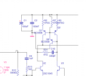
Is this is the low resolution you are referring to?
G.Kleinschmidt said:
You really don't get it, huh?
differences in simulation with a THD resolution of 0.001%
I did get it. That was the point i was making - that there isn't a significant difference. Go back and read my post.
Is this is the low resolution you are referring to?
Attachments
Re: Re: Re: Re: Re: I guess I have comments...

MJL21193 said:
I did get it. That was the point i was making - that there isn't a significant difference. Go back and read my post.
Is this is the low resolution you are referring to?
Re: Re: Re: Re: Re: Re: I guess I have comments...
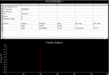
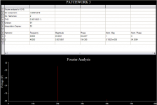
Here's your miracle mirror.
G.Kleinschmidt said:
Here's your miracle mirror.
Attachments
Re: Re: Re: Re: Re: Re: Re: I guess I have comments...
LOL!
When have I claimed that mirror to be either mine or miracle?
BTW, the difference in performance between the stock mirror, the Widlar or the 3 transistor version in real life simply will not (properly implemented) translate to the magnitude of difference in the amplifiers overall THD that your simulation results are indicating. I won't bother explaining to you why as you seem to be quite happy in your alternate universe
Bye bye.
MJL21193 said:
Here's your miracle mirror.
LOL!
When have I claimed that mirror to be either mine or miracle?
BTW, the difference in performance between the stock mirror, the Widlar or the 3 transistor version in real life simply will not (properly implemented) translate to the magnitude of difference in the amplifiers overall THD that your simulation results are indicating. I won't bother explaining to you why as you seem to be quite happy in your alternate universe
Bye bye.
Re: Re: Re: Re: Re: Re: Re: Re: I guess I have comments...
That's rich! My alternate universe? You're still good for a laugh anyway.
Glen, I don't know chit about any of this other than what my best friend, the sim, tells me. I see a higher number.
There's that thing in the signals path again that has no business having an effect on THD, voltage, current or sound quality playing games with my program. Oh the humanity!
I nicely dared you to show me the differences that I didn't see due to the low resolution of the sim, but you declined I see.
My loss.
G.Kleinschmidt said:
Bye bye.
That's rich! My alternate universe? You're still good for a laugh anyway.
Glen, I don't know chit about any of this other than what my best friend, the sim, tells me. I see a higher number.
There's that thing in the signals path again that has no business having an effect on THD, voltage, current or sound quality playing games with my program.
Oh the humanity!I nicely dared you to show me the differences that I didn't see due to the low resolution of the sim, but you declined I see.
My loss.
Frugalamp
Iam surprised that both Glen and MJL21193 haven't mentioned that you can't just retrofit a 3 transistor CM into all existing circuits and expect it to work. You would need to have an emitter follower before the VAS to add to the VBE +.94V from the VAS, to have any chance of achieving balance with this circuit as it stands. Unfortunately, Ostripper used 470 ohm CM emitter resistors in the original circuit, because he didn't have any 220 ohm or lower left in his resistor stocks at the time. He realises also, that a voltage drop of 1.1V is too high at this location in the modified circuit. (only 400mV approx. across the input side transistor of the CM.)
Incidentally in my originally posted , modified Silicon Chip circuit, I couldn't use the added diode method, or the 3 transistor CM without further modifications of the circuit, as the difference between the LTP collector voltages was only 363mV.
Please give the guy a break, he is only learning what you both take for granted. How about some constructive suggestions to OS, instead of just posting criticism based on simulator results ?
Perhaps you could even try private communication with him, instead of belittling his efforts openly?
I notice that Lineup is offering OS plenty of helpful advice.
SandyK
Re: Re: Re: Re: Re: Re: Re: Re: Re: I guess I have comments...
Clearly.
MJL21193 said:Glen, I don't know chit about any of this other than what my best friend, the sim, tells me.
Clearly.
Re: Frugalamp
Well the ISP I'm currently on blocks the host he's using for his images.
Supposing that the circuit is already working and designed properly with a stock current mirror, the the base diode fudge or the third base current "helper" transistor can be added with no further modification. Also, there is no requirement for the LTP collector voltages to be exactly equal for the current mirror to work properly.
Cheers,
Glen
sandyK said:Iam surprised that both Glen and MJL21193 haven't mentioned that you can't just retrofit a 3 transistor CM into all existing circuits and expect it to work. You would need to have an emitter follower before the VAS to add to the VBE +.94V from the VAS, to have any chance of achieving balance with this circuit as it stands. Unfortunately, Ostripper used 470 ohm CM emitter resistors in the original circuit, because he didn't have any 220 ohm or lower left in his resistor stocks at the time. He realises also, that a voltage drop of 1.1V is too high at this location in the modified circuit. (only 400mV approx. across the input side transistor of the CM.)
Incidentally in my originally posted , modified Silicon Chip circuit, I couldn't use the added diode method, or the 3 transistor CM without further modifications of the circuit, as the difference between the LTP collector voltages was only 363mV.
Well the ISP I'm currently on blocks the host he's using for his images.
Supposing that the circuit is already working and designed properly with a stock current mirror, the the base diode fudge or the third base current "helper" transistor can be added with no further modification. Also, there is no requirement for the LTP collector voltages to be exactly equal for the current mirror to work properly.
Cheers,
Glen
Re: Frugalamp
Hi,
Have you been reading the posts?? I certainly haven't been criticizing OS's amp. I have been teasing Glen about his girlfriend - Madam Current Mirror.
I have been showing the results of the 3T mirror on my own amp, which does have an EF before the VAS and lower value emitter resistors on the mirror.
More simulation BS for all of you magical tweakers, I'm sure.
sandyK said:
Please give the guy a break, he is only learning what you both take for granted. How about some constructive suggestions to OS, instead of just posting criticism based on simulator results ?
Perhaps you could even try private communication with him, instead of belittling his efforts openly?
I notice that Lineup is offering OS plenty of helpful advice.
SandyK
Hi,
Have you been reading the posts?? I certainly haven't been criticizing OS's amp. I have been teasing Glen about his girlfriend - Madam Current Mirror.
I have been showing the results of the 3T mirror on my own amp, which does have an EF before the VAS and lower value emitter resistors on the mirror.
More simulation BS for all of you magical tweakers, I'm sure.
Boy, Boy.
It is as usual when some post about a specific amplifier.
We can be glad if 25% - 30% is actually On Topic.
The rest is a lot of noise, unfortunately.
In future when people want to know about how to build this nice amplifier,
they may be scared off by annoying posts with almost zero value.
(I know some of my posts, too, can belong to this bad category )
)
->>There should be a special parallell forum for post boxing
->> Each Topic started should have one such parallell thread,
->> only for to fight to gain personal points in this audio community.
This would keep all the valuable and constructive posts in topic undisturbed.
============================
Ostripper.
I really love your layout of schematic. I mean the background color, how you have placed transistors etc.
Just beautifully done. Very easy to read your schematic
About the amplifier.
Not much to remark. It is what I would call a schoolbook amplifier.
And with school book example we mean that there is not much to add. Just to see and learn.
It is all done most properly
Lineup
It is as usual when some post about a specific amplifier.
We can be glad if 25% - 30% is actually On Topic.
The rest is a lot of noise, unfortunately.
In future when people want to know about how to build this nice amplifier,
they may be scared off by annoying posts with almost zero value.
(I know some of my posts, too, can belong to this bad category
)->>There should be a special parallell forum for post boxing
->> Each Topic started should have one such parallell thread,
->> only for to fight to gain personal points in this audio community.
This would keep all the valuable and constructive posts in topic undisturbed.
============================
Ostripper.
I really love your layout of schematic. I mean the background color, how you have placed transistors etc.
Just beautifully done. Very easy to read your schematic
About the amplifier.
Not much to remark. It is what I would call a schoolbook amplifier.
And with school book example we mean that there is not much to add. Just to see and learn.
It is all done most properly
Lineup
lineup said:
Not much to remark.
You ready to go a few rounds, Lineup?
Is the VAS running a bit hot?

Lineup,
And I really like your web persona where you strive always to give credit where it is due..... it is so easy to criticise, to look down upon others, and you always attempt to see the positive, like Carlos.
This makes such a difference to life......
I too think OS is doing damn well, it's a textbook design, everything done properly.
If the 'helper' transistor has the same beta as the VAS device, exactly as Glen has said already, then there are no current imbalances at all, and all that might remain is to ensure that the drone side runs at the same potential as the active side, perhaps by using a simple resistor in the collector.
Drawing an easily read schematic is something of an art. I agree, Lineup.
Hugh
By sandy K - Please give the guy a break, he is only learning what you both take for granted. How about some constructive suggestions to OS, instead of just posting criticism based on simulator results ?
Quite to the contrary ,I welcome constructive criticism as it just
leads me to more knowledge. I rebuilt/cased my amp today
changed the CM 470R's to 220R's and various other changes.
Thanks to lineup, I been playing around with "real' tranny models
in my ltspice , still a novice but since I repair PC's my software
"learning curve' is days not months.
One cool thing I learned w/spice is the reason for R9-C3 at
the CM collectors, It rolls off OLG > 50k ...perhaps this is why
this self amp doesn't like to be an oscillator.
Also seen is the effect of the 220R emitter resistor change.
Supposing that the circuit is already working and designed properly with a stock current mirror, the the base diode fudge or the third base current "helper" transistor can be added with no further modification
Here, just to see whether the effect was either "psycho"

or as AKSA said "psychoacoustical" I put a switch at BE of the 3rd
tranny. First I tried this w/headphones w/resistor(scary)no
thump! then I tried speakers, first w/ac-dc, then turned volume down, threw switch, viola!
With rock little difference is heard, but with vivaldi or such its
like a "stereo wide" effect. Strange to me too, for my LTspice showed
very little difference sim wise. A mystery.
Here is the updated schema of changes..
An externally hosted image should be here but it was not working when we last tested it.
P.S. Q-X = mmbt6520 (350v hfe 200)
Just to clear the air, my design goals are , under 20US$ per amp,
flexible mounting options(L-bracket, direct 90,or flat), non-
catastrophic failure (no burnt boards),and no freakin' oscillators.
DX E-mailed me saying that a Self amp cannot sound good..
I'm not mad with this and even invited him to comment here.
I have this amp , a couple of P3a's(bootstrap CS),and my
sanyo receiver. With the same speakers everywhere (120W sony
3-ways) so I can hear the differences (I can play the same
MP3 or movie on the whole network at the same time).
Back to Eagle and LT..
OS
Or a trimmer...By AKSA - perhaps by using a simple resistor in the collector
So easy to add/remove things from this design when I,m
finished making "perty" toner tranfer boards, I'm going to
put these to sub use, the frugal way..
OS
ostripper said:Here, just to see whether the effect was either "psycho"
or as AKSA said "psychoacoustical" I put a switch at BE of the 3rd
tranny. First I tried this w/headphones w/resistor(scary)no
thump! then I tried speakers, first w/ac-dc, then turned volume down, threw switch, viola!
With rock little difference is heard, but with vivaldi or such its
like a "stereo wide" effect.
Sorry, invalid testing method.
Get somebody else to flick the switch or not on the flip of a coin out of sight, but not when you are listening; preferably between stopping at the end and replaying the same track (with the phones unplugged in each case).
Listen to the same track 10 times in a row, note down each time which position you think the switch is in. When finished compare notes with the switch flipper.
Cheers,
Glen
AKSA said:If the 'helper' transistor has the same beta as the VAS device, exactly as Glen has said already, then there are no current imbalances at all,
Erm, that was for the case of an EF buffered VAS where the EF runs the same emitter current as the 'helper' transistor. This certainly is not the case for the circuit currently displayed in post #56 (now that I can see it on another ISP).
- Status
- This old topic is closed. If you want to reopen this topic, contact a moderator using the "Report Post" button.
- Home
- Amplifiers
- Solid State
- The Frugalamp by OS