Thank you Gaborbela....my friend Sakis, because the way Greek language
is... very direct, and sometimes hard. seems agressive..but this is because the language root.
I had problems here, even portuguese beeing the same language, but i have moved from Rio de Janeiro to this place in the Northeast... well..in Europe means you go from Spain to Croatia maybe...enormous distance and culture is also different.
3 Thousand kilometers i imagine is the distance..... and here they had Dutch invaders....strong influences..they talk very directly... they say to you.
- "Will not rent this appartment to you... or the Sony President, that Japanese, sign as a guarantee or no business between us!"
In my place, Rio de Janeiro, we had strong French influences because of French invaders...so, we have a more kind way to speak.... in the same sittuation, in Rio they would say:
- "I have something not so nice to say.... despite all my efforts to rent you the appartment, i am afraid we may not be happy in this business...some bureaucratic issues related the ones will sign the guarantee was not covered by the rules and regulations.... this way.... i will ask you to wait one more day, i will try to find a solution to our problem...can you offer someone more graduated to help us signing as a guarantee?"
Sometimes those things happens.... true, real words, sometimes are hard.
I am continuing to try your circuit...and i have made it better this time.... will continue tomorrow.
Thank you Gaborbela.
regards,
Carlos
An externally hosted image should be here but it was not working when we last tested it.
I'm sorry Carlos if you felt I'm to direct with you .
I do not want to be like that , I was tired to explain to the some of the guys yes the amp is working properly and sound great , there is amplifiers with dalington power transistors and even there are amplifiers with two pair or more darlington transistors .
If someone think the commercial amps on the line all has matched power transistors , mosfets or IC he is wrong .Even the amp cost couple thousand dollar , like some Pioneer Elite or Denon , NAD,Nakamichi etc .I talk about the big guns .
After I doubled the power transistors it was even better than with one pair power darlington .
When I read from people these not working , or these will be a bomb I get tired .
If you think a bit after 20 years I want to rebuild it .
I built over 30 amplifier until now .
I would not waste my time to build something if is not a great amp .
One more I apologize , How I wrote you are my friend , you bring a lot of life in to the forum .Also you are with great experience .
A read many of your writing on the forum , even on those amp what I didn't plan to build .
Again I'm happy to have you here in the forum and you are welcome always .
Greets from Toronto
Hello
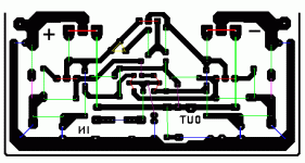
Here is my amplifier PC board lay out .These great .What I posted before you can use it but there is a small mistake . Two places 2 resistors cross each other in two places .
When I design the PC board I thought I will use two resistor on the bottom of the PC board .I forget the emitter resistors are already there .
Of course the PC board was design to the original signal transistor BC416C & 416C.
I will use BC550C & BC560C so please pay attention to the signal transistor different pin out .
Now the lay out perfect .
If you use BC414C & BC416C you just go on and use the board how it is .
If you use BC560C & BC550C please switch the lead of the transistor to feet .
Here is the correct PC layout , If you are interested I can write the parts next to the marks so you can easily build the amp if you are interested .
Please let me know !
Greets
my first amp...ooooh!
My first amp used darlingtons. MJ 2501-Mj3001 plus-minus 30 V for 20 w class A .It lasted two years before blowing the emitter resistors and the rest. Can't produce the schematic , taken from a radio magazine from the early '80s found at the flea market. I wonder if it was a bootstrapped class B with very high quiescent current -about 0,8 A . I played only disco at that time . It did his duty .Rough and tough amplifier . The 4 transistors were on the same heatsink ,together with the BD 139 . I'd just split the heatsinks , now !
My first amp used darlingtons. MJ 2501-Mj3001 plus-minus 30 V for 20 w class A .It lasted two years before blowing the emitter resistors and the rest. Can't produce the schematic , taken from a radio magazine from the early '80s found at the flea market. I wonder if it was a bootstrapped class B with very high quiescent current -about 0,8 A . I played only disco at that time . It did his duty .Rough and tough amplifier . The 4 transistors were on the same heatsink ,together with the BD 139 . I'd just split the heatsinks , now !
homemodder said:A friend of mine build this a couple of years back and he was happy with the results. Said he found schematics somewhere on the web. Based on similar topology.
This was my old design, and he can found it on my site in the Geocities. It has quite good sound even with better semiconductors. There was another version without overall feedback.
Sajti
megajocke said:
That's a pretty clever connection of the DC servo
That was the idea why I made that amplifier. Unfortunately the inverting and noninverting inputs are mixed in the schematic. I did some notes on my homepage.
Sajti
Latest tests
Hello
Here is the amp with the last mods .Now it really sound great.
Carlos if you willing to run a sim. test please do it now .
I change the power transistors , I use only one pair .
With two pair it does not sound great , the mids are a bit muddy and I missed the bass . The reason I don't know how to much darlingtons ..With unmatched darlingtons better to use one pair!
Now with one pair power darlington the sound opened up , more details the bass is punchy.
I change the original power transistors to TIP 142 & TIP147 from ST micro.
Also I change the signal BJT to JFet , I use 2SJ74BL & 2SK170BL.
Right now each side has different driver one side MJ340 & MJ350 sound nice but I have offset problem because the huge hFE difference between the PNP & NPN .
Another side I use Toshiba 2SA968 & 2SC2238 .These has less offset problem and the sound open up even more .
At the near future I will try driver from Hitachi 2SB649 & 2SD669 , I heard these are great transistors .
I can fix the offset problem 200mV .Choosing the right J fet combination or increase or decrease the 100K resistor value .Just a bit .
It really sound nice , I like it a lot . But still I want to do more test .First because no longer available the orig higher power BDW83C & BDW84C .
I'm planing to give a try to MJ11015 & MJ11016 .Al do with the TIP sound great .I'm satisfied with .
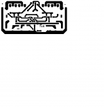
Here is the new layout . I do not have silkscreen (for the parts) I made the layout with the paint program.But if someone interested I can help , I will use color codes .
The amp has real tube like sound but better bass ,strong punchy bass not rounded like many tube amp bass .
It is very sensitive to each part , wires etc .
I use 40V PS and 120mA bias . My heat sink a bit small for higher bias .
Greetings gabor
Hello
Here is the amp with the last mods .Now it really sound great.
Carlos if you willing to run a sim. test please do it now .
I change the power transistors , I use only one pair .
With two pair it does not sound great , the mids are a bit muddy and I missed the bass . The reason I don't know how to much darlingtons ..With unmatched darlingtons better to use one pair!
Now with one pair power darlington the sound opened up , more details the bass is punchy.
I change the original power transistors to TIP 142 & TIP147 from ST micro.
Also I change the signal BJT to JFet , I use 2SJ74BL & 2SK170BL.
Right now each side has different driver one side MJ340 & MJ350 sound nice but I have offset problem because the huge hFE difference between the PNP & NPN .
Another side I use Toshiba 2SA968 & 2SC2238 .These has less offset problem and the sound open up even more .
At the near future I will try driver from Hitachi 2SB649 & 2SD669 , I heard these are great transistors .
I can fix the offset problem 200mV .Choosing the right J fet combination or increase or decrease the 100K resistor value .Just a bit .
It really sound nice , I like it a lot . But still I want to do more test .First because no longer available the orig higher power BDW83C & BDW84C .
I'm planing to give a try to MJ11015 & MJ11016 .Al do with the TIP sound great .I'm satisfied with .
Here is the new layout . I do not have silkscreen (for the parts) I made the layout with the paint program.But if someone interested I can help , I will use color codes .
The amp has real tube like sound but better bass ,strong punchy bass not rounded like many tube amp bass .
It is very sensitive to each part , wires etc .
I use 40V PS and 120mA bias . My heat sink a bit small for higher bias .
Greetings gabor
Attachments
Last edited:
Hi gaborbela,
Interesting amplifier you have there.
I have a question for you though. You had mentioned that you tried it with a pair of extra output transistors and then it didn't sound very good. One hint you mentioned was that the emitter resistor was increased a little bit. Can you post what you had tried with that configuration please?
One last thing I do know about these designs. The bias current can be slightly positive, and the amp will tend to run hotter and hotter if left idling with no signal. Once you play music, the heat sinks may even cool down as you work the amplifier (not just short of clipping) listening to music loud - ish. Have you noticed this?
I'm glad you built this. I do have an idea how clear the sound can be with it.
-Chris
Hello
Yes you right , the amp tend to run hot not much difference when I just leave it on or listening music . I leave it on day and night .
Global warming hooks.
May be when I used it cool done a bit but not much the difference .
When I used 2 pair darlington per channel each transistor had the 100R resistor and R47 emitter resistors .
I supposed to use R33 with one pair but R47 it does not hurt.
The sound warm , clear , lively .Specially I like the sound of the piano , violin ,saxophone . Also women vocals.
The amp never ever clipped for me ??? I listening normal level mostly Jazz, Classical, Gospel ,slow bar music , folk etc .From Patricia Barber , Leonard Cohen , Diana Krall ,Eva Cassidy ,Holly Cole so on . Some instrumental Jazz also .
With one pair Darlington the sound open up more , it has more bass and goes deeper , more relaxed.
But it depend on the quality of the darlington .
I tried BDW83 /84 D type, probably they were fake ST from Ebay,China.
With the smaller BDW93/94 C type sounded much better .That is from DI-GI key .
At College Street, at the Chinese store they have TIP142/147 from ST (orig) sound great . More buddy , bit more punch ,more involving .
I want to run more test , with MJ11015/16 power darlington and Hitachi drivers etc.
The J Fet sound much better , warmer than the BC550C /560C .
Also right now I use Cardas hock up wire , I think not the best . I like solid silver or copper wire .
You don't see the emitter resistors because those are at the bottom of the PC boards.
I don't know if you agree the darlington transistors tend to sound a bit warmer than many other transistors. But not as soft as the Hitachi laterals .
Because a few component the amp is very sensitive every part .
Good PS is very important .
I will do further tests , I will inform you guys .
Cheers
Yes you right , the amp tend to run hot not much difference when I just leave it on or listening music . I leave it on day and night .
Global warming hooks.
May be when I used it cool done a bit but not much the difference .
When I used 2 pair darlington per channel each transistor had the 100R resistor and R47 emitter resistors .
I supposed to use R33 with one pair but R47 it does not hurt.
The sound warm , clear , lively .Specially I like the sound of the piano , violin ,saxophone . Also women vocals.
The amp never ever clipped for me ???
I listening normal level mostly Jazz, Classical, Gospel ,slow bar music , folk etc .From Patricia Barber , Leonard Cohen , Diana Krall ,Eva Cassidy ,Holly Cole so on . Some instrumental Jazz also . With one pair Darlington the sound open up more , it has more bass and goes deeper , more relaxed.
But it depend on the quality of the darlington .
I tried BDW83 /84 D type, probably they were fake ST from Ebay,China.
With the smaller BDW93/94 C type sounded much better .That is from DI-GI key .
At College Street, at the Chinese store they have TIP142/147 from ST (orig) sound great . More buddy , bit more punch ,more involving .
I want to run more test , with MJ11015/16 power darlington and Hitachi drivers etc.
The J Fet sound much better , warmer than the BC550C /560C .
Also right now I use Cardas hock up wire , I think not the best . I like solid silver or copper wire .
You don't see the emitter resistors because those are at the bottom of the PC boards.
I don't know if you agree the darlington transistors tend to sound a bit warmer than many other transistors. But not as soft as the Hitachi laterals .
Because a few component the amp is very sensitive every part .
Good PS is very important .
I will do further tests , I will inform you guys .
Cheers
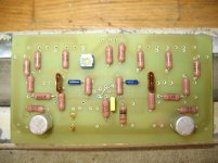
Attachments
Hello
Here is the color coded PC board if someone would like to give a try .
Don't forget the two big emitter resistor those goes under the PC board .
Red transistors , J Fet (you can use BC550C/560C) to
Green resistors
Blue capacitors
Yellow trim pot
Pink diodes
Brown jumpers 3 of them
Sorry I do not have silkscreen but if you have any question I do my best to answer it .
Greetings Gabor
Attachments
Last edited:
Hi gaborbela,
At some point, try using 2 pair again in your amp. If you use R22 resistors, you may find that it sounds far more dynamic with more punch. Going up in emitter resistance caused the sound you didn't like. This design is very sensitive to emitter resistance, and especially to the load impedance.
Can you do a rough schematic that shows exactly how your 4 transistor output was set up please?
Imagine a positive going waveform. As the E of Q1 goes high, following the base connection, the base of Q3 is also raised in voltage. Both the emitter of Q1 and Q3 are tied to their base voltages by Vbe. That means that the emitter of Q3 is related to the base of Q1 closely as the Vbe drops are similar (but not equal). As current flows through Q3 a voltage drop across P1 develops. This subtracts directly from the E-B voltage across Q3, so the base drive is reduced as the current increases. Now also look at the source of the current used to run Q3. That would be R5, a resistor. As your output voltage climbs, the current flowing through R5 is reduced - right when you need it the most! Use a CCS in those two locations (positive and negative). That will maintain the available current as your output voltage climbs. What you really need to do is somehow modulate the current into the Q1 emitter - Q3 base circuit so it increases with increasing input signal voltage. Positive feedback. You think it sounds clear now? Just you wait until these things are looked after.
The way this circuit operates is a little different from the classic amplifier driver-output stage. The current supplied to Q3 via R5 is shared with Q1 (or stolen if you'd rather). Thermally coupling Q1 to Q3 and Q2 to Q4 creates some bias compensation. Not enough though, install some kind of bias circuit in there that becomes active as the output stage warms up.
This is one amp design I really suggest you don;t leave running all the time. Not unless you can create a very stable bias current. Also, the explanation above should explain why when you increased the emitter resistor, the sound quality suffered. If anything, you need to avoid creating voltage drops in the Q3-Q4 emitter circuits. You have to achieve this goal while trying to maintain good bias current control. These are opposing requirements, so added circuitry will probably be needed. Done properly, adding these extra parts will enhance the sound quality, not reduce it.
This is a really good circuit to study. The low level detail is amazingly good.
-Chris
At some point, try using 2 pair again in your amp. If you use R22 resistors, you may find that it sounds far more dynamic with more punch. Going up in emitter resistance caused the sound you didn't like. This design is very sensitive to emitter resistance, and especially to the load impedance.
Can you do a rough schematic that shows exactly how your 4 transistor output was set up please?
Yes, that is to be expected. This design as it sits runs out of current at some point. The outputs can not be properly driven, so the current drops as the voltage across the emitter resistor and E-B junction rises in the output stage.The amp never ever clipped for me ???
Imagine a positive going waveform. As the E of Q1 goes high, following the base connection, the base of Q3 is also raised in voltage. Both the emitter of Q1 and Q3 are tied to their base voltages by Vbe. That means that the emitter of Q3 is related to the base of Q1 closely as the Vbe drops are similar (but not equal). As current flows through Q3 a voltage drop across P1 develops. This subtracts directly from the E-B voltage across Q3, so the base drive is reduced as the current increases. Now also look at the source of the current used to run Q3. That would be R5, a resistor. As your output voltage climbs, the current flowing through R5 is reduced - right when you need it the most! Use a CCS in those two locations (positive and negative). That will maintain the available current as your output voltage climbs. What you really need to do is somehow modulate the current into the Q1 emitter - Q3 base circuit so it increases with increasing input signal voltage. Positive feedback. You think it sounds clear now? Just you wait until these things are looked after.
The way this circuit operates is a little different from the classic amplifier driver-output stage. The current supplied to Q3 via R5 is shared with Q1 (or stolen if you'd rather). Thermally coupling Q1 to Q3 and Q2 to Q4 creates some bias compensation. Not enough though, install some kind of bias circuit in there that becomes active as the output stage warms up.
This is one amp design I really suggest you don;t leave running all the time. Not unless you can create a very stable bias current. Also, the explanation above should explain why when you increased the emitter resistor, the sound quality suffered. If anything, you need to avoid creating voltage drops in the Q3-Q4 emitter circuits. You have to achieve this goal while trying to maintain good bias current control. These are opposing requirements, so added circuitry will probably be needed. Done properly, adding these extra parts will enhance the sound quality, not reduce it.
This is a really good circuit to study. The low level detail is amazingly good.
-Chris
Hello
Now I need to sit done and study all what you wrote .
My question were do I start to modify the circuit ? I want to do it step by step . So to get some experience.
I was very upset with the two pair power transistor . One day I just thought what would happen if I remove one pair .
Originally the amp was designed with one pair power transistor !
For safe issue I started to use two pairs.
At first it was supplied by +/-51V. Someone suggested to me lower the power supp voltage and increase the current .
That is how I know with higher bias it sound better .
I thought because the power transistors are not matched (I don't know how)that is the reason the sound got muddy .Ad the bass rounded done like some tube amp.
After I removed one pair power transistor the amp sounded total different . Like not the same amp .
OK I will make a sketch and I'll posted to you .
I still believe the amp didn't clipped because I never push it hard .
I used 8W SS amplifier and 2W Philips tube amp to .
What I want to say I'm not after the Watt , more interested on the sound quality .
Of course if we can make it better I'm more than open to do so .
I just redesigned the PC board a couple days a go for one pair power transistor .
It is very interesting when first I doubled the power transistors the sound get fuller and somehow better more punch.
That was 18-20 years a go . Now with two pair it get much worst than one pair .
I do not understand these at all .
I thought because the orig power transistors are no longer available or only some copy, fake etc.
Believe me my friend after 20 years still use these amp. He uses regulated power supp.
He run the amp at 400mA bias .
I do not think the power transistors run low current . I got some ISC Chinese BDW83C/84C. And even with two pair when I powered up and I set up the bias at 120mA they gone ,smoked .
One think I never heard with the first amp, the power is on, and when I start play the music for a few sec I hear some noise . I never heard that before just now .
Otherwise it really sound great . I know it can be better . I still has the filling the amp has a bit less dynamic than at the first time . It is interesting at that time I used cheap resistors , capacitors , magnet wire for hock up wire and it sounded better !
Greetings
Hello
Here is the schematic with the two pair power transistor .
I cleaned up a bit so you can see it better .
The red is the second pair transistor with the added resistors
The green is the feedback, just I made it clearer a bit.
I wait on your opinion !
Greetings
Gabor
Here is the schematic with the two pair power transistor .
I cleaned up a bit so you can see it better .
The red is the second pair transistor with the added resistors
The green is the feedback, just I made it clearer a bit.
I wait on your opinion !
Greetings
Gabor
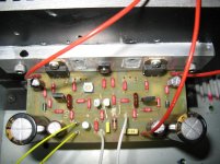
Attachments
- Home
- Amplifiers
- Solid State
- My first DIY amplifier 20 years a go