Just a quick note as I build this power amp many years ago.
The amp sounded great but was unreliable. This proved to be because the specified power supply voltage was just too high.
In the original 1979/80 version the power transformer was 30-0-30, and could cause break down of the input devices.
I note in this version it's 28-0-28, I ended up using 25-0-25,
as a safe option.
I also added some over current protection set to 3 amps, which saved the output devices from thermal runaway when I didn't get them perfectly flat on the heat sink.
THE ONLY REASON
i would built a think like that is for fun ....
in any case you decide to do so keep in mind that your outputs have to be made my the same mom like you cannot have a bdv 66 from philips and a bdv 67 from ST ...
the reason is that they may say that they are bdv 66 or 67 but due to the construction inside might have diference ( not matching ) inside depending on the part number ......
any way i would go for ON SEMI MJ 11015-16 FAR MORE BETTER AND ROW BUST .....
to symon
the above reason is NO 1 reason for thermal runaway cause in this case you adjust idle to specs but that apply only when amp is on idle if you power it up then things are pretty much messed up
measuring voltage drop on every emmiter resistor might be some help cause you may find some diference there but still that cannot tell you much since even if you do find a diference there is nothing you can do about it ......its just an indication .....
regards sakis
I built one of these too, but I used TIP transistors for the outputs. Transformer was 56VCT, with 26,000 uF per rail for a stereo amp.
ETI (though not the Canadian edition) later published an input buffer board for this amp since in the stock form it has a pretty low input impedance. I've got a photocopy someplace, which I ought to scan.
I blew a channel once by shorting the speaker cable, and more recently blew both channels when I used it as a DJ monitor amp. I'm leaning towards filling the box with LM3886's instead...
ETI 470 + ETI471 Schematic
Hi I'm also looking for these circuits - a blast from the past !
Can anyone help ? The link about does not work now after 4 years. Any info re the Electronics today international ETI Magazine article would be gratefully received.
I think it's from ETI Ether July Or May or June or July or most likely or December 1979 - It's 1979 anyway.
Many many kind Thank yous !")
Simon
Hi I'm also looking for these circuits - a blast from the past !
Can anyone help ? The link about does not work now after 4 years. Any info re the Electronics today international ETI Magazine article would be gratefully received.
I think it's from ETI Ether July Or May or June or July or most likely or December 1979 - It's 1979 anyway.
Many many kind Thank yous !
Simon
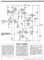
ETI-470 Amplifier - Spot the capacitor of doom
This was among my first 60W power amplifier builds a long time ago.
What is that tantalum C3 doing there?
Excerpt from: http://solaris.no/electronics/power_amp/ETI480/ETI480_theory.pdf:
ETI-470 “Designed by Phil Wait from an original circuit by [West Australian] Trevor Marshall”
'A 0.47μF tantalum connected the bases of the input differential amplifier pair. “Input lag compensation is provided by C3, limiting the slew rate of the amplifier to reduce high frequency intermodulation”. This gave the amplifier a very specific requirement to be driven from a very low impedance source to avoid distortion at higher audio frequencies. ETI needed themselves to publish an “interface” circuit (again by Phil Wait) to allow ETI-470’s to be appropriately driven in their Series 4000 stereo amplifier project.'
It used TIP142/147 Darlingtons and the VAS ran hot.
ETI Canada called it the Series 4000.
I just found my old PCBs and schematic, saw the cap
Attachments
it rolls off the trebleThis was among my first 60W power amplifier builds a long time ago.
What is that tantalum C3 doing there?
I expect Q7 is even hotter !Excerpt from: http://solaris.no/electronics/power_amp/ETI480/ETI480_theory.pdf:
ETI-470 “Designed by Phil Wait from an original circuit by [West Australian] Trevor Marshall”
'A 0.47μF tantalum connected the bases of the input differential amplifier pair. “Input lag compensation is provided by C3, limiting the slew rate of the amplifier to reduce high frequency intermodulation”. This gave the amplifier a very specific requirement to be driven from a very low impedance source to avoid distortion at higher audio frequencies. ETI needed themselves to publish an “interface” circuit (again by Phil Wait) to allow ETI-470’s to be appropriately driven in their Series 4000 stereo amplifier project.'
It used TIP142/147 Darlingtons and the VAS ran hot.
I recommend you change the input and feedback capacitors and add some RF filtering.ETI Canada called it the Series 4000.
I just found my old PCBs and schematic, saw the cap
try C1 = 22uF bi-polar or two 47uF bi-polar in back to back formation.
try C4 = 1m5F (1500uF) with protection diodes across it.
Add an 1nF to 2n2F capacitor after the input 82r to Signal Return.
Check your PCB layout:
Is Input Return connected to R5 and to C4, by a very short, very low loop area, trace? i.e. not taken to some remote star?
The Vbe multiplier lacks a protection limiter in case the wiper lifts off momentarily.
The protection transistor Q9 starts to enter limiting when the current through R13 hits ~33mA. That allows ~66mA through Q7. That seems quite high to me. And reaches full limiting when Icq7 @ ~100mA
Last edited:
I built this amp in IIRC 1980/81. I replaced the output devices with TO3 MJ15xx types.
Served as my main power amp for many years until I scrapped it off in about 1994/5. I think the rail voltages I ran were about +-35VDC. I used the rectifier and capacitor bank assembly from a Marantz 240 that I had bought in 1976/7 that blew up and I was unable to repair. I also used the speaker switch on delay from the Marantz - worked very well.
The resistor feeding output damping network that has the caps returning to the rails had a habit of burning out - clearly some HF oscillation but I never tried to fix it - seemed to work ok.
Thanks guys, hmm I also built it in 1981 and yes I thought it oscillated cooking the damping resistors. Hard to tell many parts were hot at idle.
As I recall, it had poor PSRR and a fair bit of hum regardless of grounding and 10,000uF filter caps. I used the magazine's PCB artwork.
There's no compensation anywhere, so I wonder if it's stable enough to have C3, not that it's sane practice. I think it's just a bodge. If you want to roll off the high-end to prevent TIM, cap across R5 is what I usually see.
Attachments
I built this way back and experienced the same instability. As a young whipper snapper (probably 15 years old) it frustrated the hell out of me.
It had a habit of taking out the output devices which in the early 80s were very expensive!
As nostalgic as the series 4000 is to me, i would not build one, and if I found one would run it up only for fun. It worked once set up, but was too cantankerous for me to want to connect it to an expensive speaker these days.
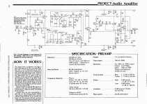
This is the Series 4000 Preamplifier schematic to go with the amplifier.
I built it and the phono preamp rated 0.015% THD sounded nice but noisy. Somehow max. hiss occurs at a 47k source, so it is optimized for noise lol.
I thought the ETI amplifiers went up in numbers, so the ETI-480 replaced this ETI-470. I'm not entirely sure as they were renumbered/renamed for reprints in ETI Magazine in Canada.
Attachments
Last edited:
I built this amp in IIRC 1980/81. I replaced the output devices with TO3 MJ15xx types.
Served as my main power amp for many years until I scrapped it off in about 1994/5. I think the rail voltages I ran were about +-35VDC. I used the rectifier and capacitor bank assembly from a Marantz 240 that I had bought in 1976/7 that blew up and I was unable to repair. I also used the speaker switch on delay from the Marantz - worked very well.
The resistor feeding output damping network that has the caps returning to the rails had a habit of burning out - clearly some HF oscillation but I never tried to fix it - seemed to work ok.
Can't reminder what I did about the OPS. I think I used BD139/140 for drivers. 37 years ago - the memory is dim
Copies of ETI magazine available here ETI: British and Australian Electronics and Hobbyist Magazine
This series ended with the 6000 model, designed by Professor David Tillbrook, from Uni of Sydney (maths dept IIRC).
It was a complex amp, with three diff pairs in cascade, but it sounded very, very good and established a reputation for a true high end amp.
David spent a lot of time on the stability - perhaps his great interest because of Bode and Nyquist - but it really finished the series, nothing better was produced by ETI to my knowledge.
HD
- Status
- This old topic is closed. If you want to reopen this topic, contact a moderator using the "Report Post" button.
- Home
- Amplifiers
- Solid State
- ETI 470 + ETI471 Schematic