Inspired by other posts on the lightspeed attenuator, I decided to make one device of my own. It took me some time to finish the first prototype, but it was worth the effort. The device proved to sound well and to satisfy the demands and needs of my hearing apparatus. ")
I started from the idea that I needed a preamp with an input selector, volume control and visual indication of what has been currently set. A few problems arose from the requirements, the first one, and the most important one, was the casing and buttons + potentionmeter covers.
Most of the stuff for make up of the casings is relatively easy available and affordable. However, I tended to avoid any drilling and cutting which was excessive.
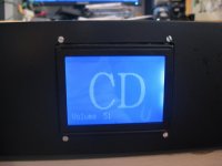
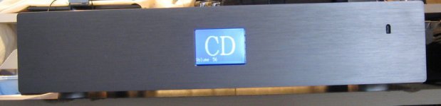
Therefore, I took the path of making a preamp with a remote controller only and with a graphic LCD on the front panel. No buttons, no pots, no switches. Just one graphic LCD on the front.
In order to realise this, I took the following parts:
1. PIC 18F4520. I have a couple of these in the drawer and they are my favorite,
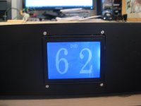
2. Graphic LCD with blue backlight and white graphics,
3. Microchip DAC MCP6024. This chip drives the optocouplers,
4. Silonex NSL32SR3S and
5. Opamp AD826, by Analog Devices.
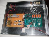
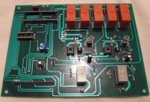
The concept is very simple: PIC drives DACs, which drive optocouplers. Volume level and selected input is shown on the graphic LCD. Optocouplers' inputs and outputs are buffered with AD826 connected as unity gain buffer amplifiers.
I made separate power supplies for analog and digital section. Analog power supply is +-12V and it drives the opamps. The digital power supply is +5V and +12V and it drives relays, PIC and optocouplers.
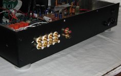
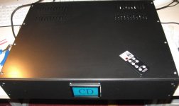
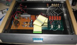
This is how it all looks. To remind you, it is just a prototype, I indend to keep the box, but I will rewire evertying after re-routing the PCBs. Also, I bought Takamisawa relays and silver wire in effort to make the device really outstanding. Let's not forget that I plan to add a nice aluminium front panel which is getting ready these days.
So far this "preamp" showed an excellent performance, maybe a little sharp on the trebles (ad826?), but the general sound picture is very neutral and with excellent bass. My impression is that this preamp sounds better than Onkyo integra which I have been using for some time. It is so transparent, that I have impression that it is not there at all
This is one very small investment, but a great gain. Also, it was a great pleasure making it.
Suggestions and comments are welcomed.
I started from the idea that I needed a preamp with an input selector, volume control and visual indication of what has been currently set. A few problems arose from the requirements, the first one, and the most important one, was the casing and buttons + potentionmeter covers.
Most of the stuff for make up of the casings is relatively easy available and affordable. However, I tended to avoid any drilling and cutting which was excessive.
Therefore, I took the path of making a preamp with a remote controller only and with a graphic LCD on the front panel. No buttons, no pots, no switches. Just one graphic LCD on the front.
In order to realise this, I took the following parts:
1. PIC 18F4520. I have a couple of these in the drawer and they are my favorite,
2. Graphic LCD with blue backlight and white graphics,
3. Microchip DAC MCP6024. This chip drives the optocouplers,
4. Silonex NSL32SR3S and
5. Opamp AD826, by Analog Devices.
The concept is very simple: PIC drives DACs, which drive optocouplers. Volume level and selected input is shown on the graphic LCD. Optocouplers' inputs and outputs are buffered with AD826 connected as unity gain buffer amplifiers.
I made separate power supplies for analog and digital section. Analog power supply is +-12V and it drives the opamps. The digital power supply is +5V and +12V and it drives relays, PIC and optocouplers.
This is how it all looks. To remind you, it is just a prototype, I indend to keep the box, but I will rewire evertying after re-routing the PCBs. Also, I bought Takamisawa relays and silver wire in effort to make the device really outstanding. Let's not forget that I plan to add a nice aluminium front panel which is getting ready these days.
So far this "preamp" showed an excellent performance, maybe a little sharp on the trebles (ad826?), but the general sound picture is very neutral and with excellent bass. My impression is that this preamp sounds better than Onkyo integra which I have been using for some time. It is so transparent, that I have impression that it is not there at all
This is one very small investment, but a great gain. Also, it was a great pleasure making it.
Suggestions and comments are welcomed.
Attachments
Great Job
The input and output buffers are the only thing I would change. If you have low output impedance sources and high imput impredance amplifiers the buffers are not needed. Input impedance of 500 ohms or less and input of amp at 47K or higher works great without buffers.
I like your design, this unit would sell for 3 -5K here if built by a boutique manufacturer. The LCD, remote, and PIC's are cheap to source, but are really expensive in small volume audio gear.
George
Hi Zristic
I am sitting here right at the moment at my desk and experimenting with a similar idea. I am measuring the resistance / volt curves of my test gear.
I am using an Atmel µC, a LTC1655L DAC and a 32SR2S!
I will try to build it in a fixed series, optocoupler shunt configuration with a JFET buffer (NP). The thing what spoils me most is the temperature offset of the Silonex parts. 48832 Bits now results in 18840 Ohm, half an Hour later it is 20740 Ohm! Disgusting!
Is the SR3 better in this issue? What is your lowest attenuation?
Nice work you did so far. Nice PCB you made!
I have not done any measurements, yet. To be honest I was skeptical about all of this, I did not believe that it would work at all. So I made the prototype to see how it would behave. As soon as I hooked it in the system I realized it is all well, so now I am enjoying it for a while, before I dismantle it again and perfom measurements.
I have a storage scope with FFT and I will also measure the transfer curve of the device. Of course, I will put all the measurements here.
I was recommended to take 32SR3S by Silonex because "they perform better and are more popular".
We'll see.
I have a storage scope with FFT and I will also measure the transfer curve of the device. Of course, I will put all the measurements here.
I was recommended to take 32SR3S by Silonex because "they perform better and are more popular".
We'll see.
Tolu said:Thanks, but I am more interested in the DAC part. The MCP6024 is a quad-opamp so I don't understand how you use it for LED driving. What DAC are you using?
What type of opamp do you use and why two?
Tolu, it is very simple: DAC output is connected to the first opamp input. Opamp has the gain of +2. Opamp output is connected to the net "VCONTROL_LEFT".
DAC is max541, its reference is 2.5V. The output of DAC is 2.5V maximum. The opamp amplifies the output of DAC and gives +5V max at its output.
There are two configurations of the kind, one per each channel. They use two opamps and two DACs. The rest two opamps in MCP6024 are not used.
At the end it is not really important which DACs and opamps you use. The concept is the same and you can make many variations on the subject, with the same effect.
This weekend I will measure some parameters of this device and I will publish them here.
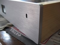
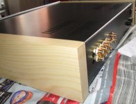
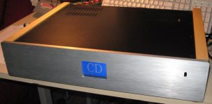
I want to start selling these devices. Here is the first real prototype- it needs few corrections in measures, and in internal wiring, but this is how I intend that it looks.
The next step is measuring electrical parameters. Box took me too much time, but fortunately it is done very well and only needs few little corrections.
The idea is to have silver mask, silver box and white wood in one variant, but also a black mask, black box and cherry wood in another version.
Suggestions and comments are welcomed.
Attachments
[more images
Attachments
- Status
- Not open for further replies.
- Home
- Amplifiers
- Solid State
- Lightspeed Attenuator + Input selector