Hi Michael,
Why don't you just buy one") It's a worthwhile investment. A 10/1 probe consists of a precision 9 meg resistor in combination with the 1 meg of your 'scope.
It's a worthwhile investment. A 10/1 probe consists of a precision 9 meg resistor in combination with the 1 meg of your 'scope.
The trimmer cap is variable -- like a little beehive trimmer you used to get in transistor radios. You will never do it with fixed values.
A homemade one will never come close to the correct performance IMO as there is too much stray capacitance/inductance etc from all the joints and separate components. It's just one of those things you can't make as well as the commercial product.
Why don't you just buy one
It's a worthwhile investment. A 10/1 probe consists of a precision 9 meg resistor in combination with the 1 meg of your 'scope. The trimmer cap is variable -- like a little beehive trimmer you used to get in transistor radios. You will never do it with fixed values.
A homemade one will never come close to the correct performance IMO as there is too much stray capacitance/inductance etc from all the joints and separate components. It's just one of those things you can't make as well as the commercial product.
i went to buy one set. but when i saw that is poor quality and price they tag, so i didn't. now thinking, i have to buy a pair of probe.
There price is S$20 each so i will need two pcs. i have go there and see more to choice one pair of good quality.
have to wait till get the good one.
There price is S$20 each so i will need two pcs. i have go there and see more to choice one pair of good quality.
have to wait till get the good one.
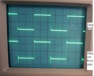
finally i bought probe for scope. now i test the amp and found two signals are not same when i attached to the amp, in and out. here i show the image of input and output 1khz.
absolutly amp problem. i don't know what could be problem in amp? there are two side showing like ripple.
absolutly amp problem. i don't know what could be problem in amp? there are two side showing like ripple.
Attachments
there you go michael
Well done ....you are starting to get somewhere ..... now the next step will be to have a nice dummy load ....and start loading your amps and have real test conditions .
Then again you will start to realize how critical lay out is and no matter that your designs are really futuristic ( i actually like them very much ) but the thing is that in such lay out will be very easy to start to "pick up" problems here and there .
Load them !!!!!! there also i would like to give some advice but please dont missunderstand it :
Please follow other member's advice and make a dummy load to start to test your amps in real life conditions BUT !!!! start to make your tests in low power levels ......then proceed with testing but increase power one step at the time .
At this layout it is very possible thta your amps oscilating and also due to the power arangements and distribute your amps will not stand 100% operation at load conditions .
On the other hand if you dont burn you will never learn ......All of us have been there sometime ( anyone who said not is a big lier )
regards sakis ......you are in a good track
thanks for your comments.
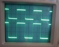
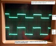
i don't mind at all. i am learing from you guys. here are lots to learn. now i used 1khz to the amp using pot to control volume. the volume cable is not for audio so there is a ripple at the corner cause by the cable. now you can see 75% volume was used to check. i used real 8ohms speaker for output (short time). here is the pic.
i don't mind at all. i am learing from you guys. here are lots to learn. now i used 1khz to the amp using pot to control volume. the volume cable is not for audio so there is a ripple at the corner cause by the cable. now you can see 75% volume was used to check. i used real 8ohms speaker for output (short time). here is the pic.
Attachments
That looks very much better Michael.
Now does the output of your amp alter when you connect the load. It should remain essentially the same but could also increase or decrease in amplitude. What does it do ?
Try and get hold of some high power resistors, they are quite cheap, even 25 and 50 watt ones for testing. An 8 ohm speaker is just a nominal value. The actual impedance will vary from perhaps as little as 3 ohms to as much as 30 or more depending on the frequency.
I know you have read this before,
http://www.diyaudio.com/forums/showthread.php?s=&threadid=126370&highlight=why+layout+matters
That other DIY member in post #1 was guess who
here it would be very nice
A common effort from expirienced forum memebers ( i am so happy that we have plenty) to may be create a list of procedures that can also be a reference to other not expirinced forum members .....
Something like
***NO LOAD CONDITIONS ****
1) 1KHZ SINEWAVE 10% POWER
2) 10KHZ SINEWAVE 10% POWER
3)100KHZ SINEWAVE 10%POWER
And then again
***NO LOAD CONDITIONS ****
1) 1KHZ SINEWAVE 50% POWER
2) 10KHZ SINEWAVE 50% POWER
3)100KHZ SINEWAVE 50%POWER
And then something like
***RESISTIVE LOAD CONDITION *****
TESTS RELATED TO FREQUENCY VERSUS POWER
Or again
*****CAPACITIVE LOAD *****
WITH ALL FREQUENCY SINE OR SQUARE WAVE PROCEDURES ....
it would be very nice if also michael and other forum members have some questions answered like for example : can you apply 10khz square wave under resistive loads to observe the wave form ???? and if so in which level of power ?????and if so for how long time ????? and the same goes on for sine wave and/or other frequencies
it is possible that some of us do not know that actually a burst of a continue sinewave frequency in a quite high level might very well rip your outputs completely if somethings goes wrong and some overdrive or ocilation is there (genearlly instability )
hi mooly,
i have read again your past thread about signal. i understood the point, i will check it today. it can be cause by the gnd. i thought it was cause by the cable too long and the type. anyway i feel lots of fun using osc....really fun to learn.
your question was: Now does the output of your amp alter when you connect the load. It should remain essentially the same but could also increase or decrease in amplitude. What does it do ?
i saw it dsn't change the polarity because as the same time i attached the volt meter at output but i didn't see about the amplitude. i will check it out.
hi sakis,
i will do as you said. i have to understnad the signal.
currently i used my scope 1khtz signal to check, i am making my own "sign wave sigal generator". I have to wait for while.
i will show all the test result slowly.
how to know that it is ossilating?
- Status
- This old topic is closed. If you want to reopen this topic, contact a moderator using the "Report Post" button.
- Home
- Amplifiers
- Solid State
- my first oscilloscope