The DVM is essential, you can't do anything without it. Solder braid is well braid ! more correctly it is copper braid with a flux soaked into it. The idea is to hold it against the solder on the part you want to remove, apply the iron and the solder gets wicked up into the braid. It's good, very good but you need to practice. Any scrap PCB's around ? The soldering iron also needs to be good, and not too small a bit in it --- you need plenty of heat for large components. You need the proper solder as well.
The MJ2955, there must be local equivalents you can get, but we need to test them first. TIP2955 are the same, probably more common.
Can you see the type number of the other transistors in the power amps. Might help if you post them so we can see what they are.
The MJ2955, there must be local equivalents you can get, but we need to test them first. TIP2955 are the same, probably more common.
Can you see the type number of the other transistors in the power amps. Might help if you post them so we can see what they are.
Mooly said:The DVM is essential, you can't do anything without it. Solder braid is well braid ! more correctly it is copper braid with a flux soaked into it. The idea is to hold it against the solder on the part you want to remove, apply the iron and the solder gets wicked up into the braid. It's good, very good but you need to practice. Any scrap PCB's around ? The soldering iron also needs to be good, and not too small a bit in it --- you need plenty of heat for large components. You need the proper solder as well.
The MJ2955, there must be local equivalents you can get, but we need to test them first. TIP2955 are the same, probably more common.
Can you see the type number of the other transistors in the power amps. Might help if you post them so we can see what they are.
I stand violently corrected, two MJ2955's are present, but the other two are 2N3055's, again, made by Motorola.
The First MJ2955's markings are:
MJ2955
T8748
Motorola Logo
The second MJ2955's markings are:
Motorola Logo
MJ2955
MEXICO
9319
The first 2N3055's markings are:
2N3055
T8747
Motorola Logo
The second 2N3055's markings are:
Motorola Logo
2N3055
MEXICO
9416
I know its alot, but I have a gut feeling that the numbers are in reference to something.
Each one of these four transistors have 4 contacts on their underside.
Im not sure what else could be a transistor, so Ill work faster on getting that photo.
Mooly said:Hi Alex,
2N3055 and 2N2955, in the "round" TO3 package-- not flatpacks.
We are at the beginingTransistors -- those 3 legged things, such as BC546 or 2SD or 2SA etc --- have a look
There are black, green and a single gold '3 legged things'
Most of them have a hole through them. There are some smaller ones without holes, are these also transistors?
All five black ones are D669A's with the following markings:
7
C J5
Both green ones are B649A's with the following markings:
C
7 H5
The gold one is a B649A ALSO! but it has the same markings as the green ones.
EDIT: NOTE, ALL THESE HAVE HOLES THROUGH THEM!!!
Finally, are those smaller ones which look like half circles transistors too?
Nothing too scary there !! 2SD669A are NPN and the 2SB649A are PNP. 99.999% of the time any 2SD number is NPN and any 2SA is PNP. They are a "complementary pair" and these will be the driver transistors for the outputs.
Its just the main number thats needed such as BC546B etc , any other numbers are just production codes and date codes.
All those plastic semi circles are transistors, all will have 3 legs.
You need that meter !!
Its just the main number thats needed such as BC546B etc , any other numbers are just production codes and date codes.
All those plastic semi circles are transistors, all will have 3 legs.
You need that meter !!
By the way, you were dead wrong about the motorola ones being replaceable by the tip2955's.
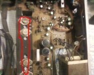
Its a 4 solder point transistor that DOESN'T stand.
Im attaching a low definition photo.
The four circles screwed to the board (with one a little out of sight) are the first 4 transistors I identified, but I haven't pointed out two 3 legged transistors, black, screwed inbetween two transistors at a time, 2 total.
EDIT: Gotcha, That was a poor mistake on my end, I need new sodium lamps...>_>
Anyway, You were right, but would I really replace something as big as the ones I have now with the small little 3 legged device?
Attachments
Hi Alex,
You replace like for like, possibly using equivalents, but always in the same package (for outputs anyway).
As I say, the meter is essential, don't try swapping parts without knowing what you are doing.
I have just seen your new post. Look at the link I gave. The screws are the collector terminal and the devices will be insulated from the metal heatsink by insulating washers.
You need to calm down and listen and learn if you are to stand any chance of fixing it.
So far, you've saved me from having to think twice about buying a new amp, I am not worthy!
Haha, thank you very much for all your help so far, and I will get that Digital Volt Meter!
EDIT: NAD got back to me!!!
But with some terrible news.
To be honest I'm just glad someone on the company's end got back to me!
Haha, thank you very much for all your help so far, and I will get that Digital Volt Meter!
EDIT: NAD got back to me!!!
But with some terrible news.
Hi Alex,
I received your voice mail. Unfortunately, due to the age of this unit, we do not have anything that we can e-mail. We have a hard copy available, cost is $45.00 and we can only ship to the US.
Please let me know if you would like to order this.
Thanks
Ingrid
To be honest I'm just glad someone on the company's end got back to me!
I have the same problem on my nad 3130.
"some darkening of the PCB around Q504, Which is running hot but not beyond what I can touch you without burning".
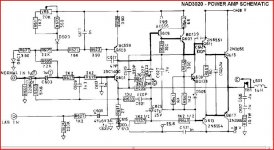
The power supply voltages are of (-34,8V) on the collector of Q504 and (+ 40,3V) on the collector of Q501. On emitters, we measure the following two output voltages: (-26,2V) on Q504 and (+ 36,2V) at the collector of Q501. There is a difference of 10 V.
It's normal? I don't find,on the net, a diagram shows the values of voltage, can you help?
"some darkening of the PCB around Q504, Which is running hot but not beyond what I can touch you without burning".
The power supply voltages are of (-34,8V) on the collector of Q504 and (+ 40,3V) on the collector of Q501. On emitters, we measure the following two output voltages: (-26,2V) on Q504 and (+ 36,2V) at the collector of Q501. There is a difference of 10 V.
It's normal? I don't find,on the net, a diagram shows the values of voltage, can you help?
We would need to see the circuit to make an informed decision on what you are seeing. If its all working then there can't be much (if anything) actually wrong. Darkening of PCB's (particularly paxolin type) is very common and unavoidable where there is local heat produced. So normal in other words.
- Status
- This old topic is closed. If you want to reopen this topic, contact a moderator using the "Report Post" button.
- Home
- Amplifiers
- Solid State
- Problem with a NAD 3130