Hey techies.")
I have a bass combo amp, swr superredhead, that has an issue that I cannot really tell if its a preamp issue or power amp / section issue.
Distortion at low volumes. If I turn the amp up, it gets almost as loud as it should, and its cleaner, but she aint "off the shelf" sounding yet. Here is what I have done so far.
1. replaced the only tube in the amp. a 12ax7. this does not solve the issue. ANd I have reason to believe that the preamp section is okay. Replaced some of the preamp caps and resistors. More of the tone im looking for, but the power still is lacking a little.
So, what would you check? Caps? Resistors? Power transistors? Those are 2SC3264's. 4 of them for a 350 to 450 watt ourput. I have the trannies on order, should show up this week.
Thanks for any input peeps.
Mike
Hi Mike,
I can't say anything about your tube side with knowledge on these lacking but if I were to guess I would suspect input connectors, cables and look at solder joints on preamp cboard. Have you eliminated possibility of pickups by using another instrument?
Dont give up
Chris
I can't say anything about your tube side with knowledge on these lacking but if I were to guess I would suspect input connectors, cables and look at solder joints on preamp cboard. Have you eliminated possibility of pickups by using another instrument?
Dont give up
Chris
Are you using a passive bass plugged into the lower gain active input? That might explain the lower than expected volume.
Can you get either of the preamp clip light to come on? Your bass may have low output pickups.
Ditto the recommendation to check input conction solder joints. Even if they look OK, reheat them.
If you can post a link to a schematic, we'd be able to be more helpful. Google didn't turn one up.
Can you get either of the preamp clip light to come on? Your bass may have low output pickups.
Ditto the recommendation to check input conction solder joints. Even if they look OK, reheat them.
If you can post a link to a schematic, we'd be able to be more helpful. Google didn't turn one up.
Ill retouch the solder joints on the preamp board, then the other sections and test as I go. I wont give up on this baby. She didnt work at all when I bought her for 250. Had to replace the speakers and some fuses/fuse holders.
this is a simple issue, thats my feeling anyways.
Cant upload the pdf as its too big a file size.
this is a simple issue, thats my feeling anyways.
Cant upload the pdf as its too big a file size.
Attachments
Check the pre-amp voltages. there should be +/- 15VDC for the preamp. If one side measures 7.5Vdc then look at the power supply board. SWR uses a pair of 7.5V zener diodes in series with a paralleled pair of 5 watt resistors to drop the +/- 70Vdc from the output stage down to +/- 15vdc in most of there amps. the 5 watters in parallel have about 7.5 watts across them. the leads of the resistors are twisted together get HOT real HOT and they will melt the solder right out of the joint causing one resistor to disconnect. when this happens, the preamp voltage on that side drops to 7.5Vdc about and will cause the pre-amp to oscillate driving the output stage to full power oscillation! Its a nasty problem. and it common to all pre fender models.
I ALWAYS replace the 5 watt white coffin resistors with a pair of 10 watt Dale Aluminum houses resistors mounted to the side of the chassis with 18 gauge wire wrapped around the terminals tightly before soldering to form a solid mechanical connection. there isn't enough room in most chassis to put a small transformer, rectifiers and caps or i would have taken that route.
The speaker failure issue is very common in these models. the eminence Delta's are a much better replacement and keeps that stock sound. a very common upgrade for these.
Other SWR issues relate to the PCB standoffs on the output boards being too long. the Bias transistor leads are stretched tight and will fail internal to the transistor due to heat flexing. I cut the stand offs down 1/8" and shorten the screws the same amount. you MUST shorten the screws or they will bottom out and snap off. don't ask me how i know!
The 3264's are a very very commonly counterfieted transistor. lots of info about these make sure you get real ones! 9 out of 10 seem to be fake.
Do NOT use generic anything in these amps. they will not survive with NTE/ECG generic crap. these were very high performance amps. the output stage is flat out to 40K and the same branded parts must be used.
Fuses should be added to the secondary side of the transformer as well. SWR elected to leave them off to cut cost's and because of the slight sonic degradation that could cause. However with no B side fuses, when the Bias transistor or output transistor fails, it will smoke the PCB board into charcoal.
On the SM-900 models i always upgrade the PSU caps from the stock 6800uf caps to 15,000uf caps and it make a huge difference to the bottom end. lots more punch and 5th string sustained notes are much better.
Most of these amps were hand built and they are prone to lots of bad solder joints. I have repaired over 50 of these amps and not once have i ever had to repair a preamp stage. issues are almost always related to the front end power supply or bias transistor failures.
Zc
My Hero!!!!!
dude that gives me pretty much all the info I need.
I just won an sm900 off ebay and I am going to do the same to it.
thanks everybody.
I modded the preamp a little and will continue..NO NTE crap here!
OPA 2604's to replace the tlo72's. same manu on the output trannies. Solen caps in the preamp section. I like them more than wima.
UPDATE:
So far so good. The amp gets a little more volume to it and I changed the preamp tube to a 12AT7, wich doesnt seem to change the gain too much, but it is a little cleaner as I push it.
Hey Zero,
10 watt Dale Aluminum houses resistors ..where could I find these?
Also, the 15,000uf caps, are they the same voltage 75 or 80 volt or do you use a larger voltage rated cap as well?
I changed the opamps to 2604's and they do sound cleaner and a little more crisp..which is nice. Less noise too..never thought I;d notice, but I do.
I gig with the amp tomorrow night so Ill let you know how it goes.
The voltages off the diodes for the opamps is 14.85 volts. Now, is this good or do I need to be like a pc guy( thinking ram voltages ) and get it as exact as I can?
You also mention the Delta 10" series as replacements, Have you tried the legend series speakers? I have 16ohm in there for 8 ohm, but think I want 2 8ohm in there. That IM not too sure of yet.
The only thing I get is a peaking squeal if I hit the amp hard. But I feel this might be a little normal, if not is something oscillating?
14.80-15.20 is about normal for the outputs of 7815 regulators. have you checked the bias current on the output transistors? no bias usually results in low level distortion that goes away at higher signal levels.
you could have a bad solder connection that acts up when you whack the side of the amp causing that squealing noise (hence the old term "out of whack")
you could have a bad solder connection that acts up when you whack the side of the amp causing that squealing noise (hence the old term "out of whack")
chicago_mike said:Hey techies.
Distortion at low volumes.
Mike
I had that on one of my early amp designs that didnt have bias for crossover distortion.
Perhaps the bias is set incorrectly ?
I would suspect bias adjustment too. It's easy to see with a signal
generator and a scope, otherwise you can adjust it by ear (feed the
amp with a simple signal like 1 kHz sinus, adjust until it sounds clear).
If the amp gets too hot when idle or clips too early, you have too
much bias current...
Some professional SWR repair guy (I'm not) might know a 'normal'
range for bias current on these PAs?
lundborg said:I would suspect bias adjustment too. It's easy to see with a signal
generator and a scope, otherwise you can adjust it by ear (feed the
amp with a simple signal like 1 kHz sinus, adjust until it sounds clear).
If the amp gets too hot when idle or clips too early, you have too
much bias current...
Some professional SWR repair guy (I'm not) might know a 'normal'
range for bias current on these PAs?
If it is bipolar then you can work out a bias ballpark from the cct.
I know in my MOSFET amps it is around 7 volts bias.
I add a zener across my bias cct so it wont go much over 7 volts even if the bias cct fails. Its only a few pennies for a zener.
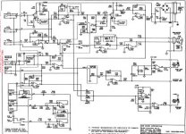
Hi guys! I'm just a neewbie in this forum so first of all I would like to say HELLO to everyone! I was lurking this forum for a long time, this place is a great source of knowledege for sure.
I found this topic while I was looking for a SWR redhead schematic, and up till now the one posted by Chicago_Mike is the best i found.. too bad is so small that I can't read it
could you please let me know where can I find a bigger version of this schematic?
thank you in advance to all you wisemen!
PS: sorry, my english is awful
You might try with the nice people at Fender, they will send you the
schematics for free, at least if you're doing a repair or mod. I don't
know what they say if you tell them you're building from scratch...
The pre-Fender SM400 schematics are on the web,
http://www.freeinfosociety.com/electronics/schempage.php?cat=1
The PA circuitry should be the same as the 350, and the preamp at
least similar I guess.
I got a spare PA unit and other PCB:s from an eBay member a while
ago (fendervender69). She might have more in store though I don't
see anything listed right now (it's scrapped 2x10 combos and 4004:s
that would be of interest for you). Their PA 2000 unit is the same as
the one in the 350, and the preamp boards are good for parts or
modding (they are OK as they are but don't have the 12AX7 tube).
/Tomas
- Home
- Amplifiers
- Solid State
- Bass amp issues, swr redhead