hi,
thanks. i just made two amps. those are not really very sweet sound quality. it's very good quality but not that kind of sweet sound. i just tested those two. Thanks to them for there circuit posted on this forum.
now I am looking for more btr sound quality with sonic sweet (i dn't know is this correct words). thanks for informing me, it dsn't have to be class a amp.
anyway i just want to get any one can post nice amp to try.
thank you.
You can always try this one of mine. This beats hand down all the amps I have compared it with, commercial and DIY, including some highly regarded Class A's, for musicality. There is a vibrancy and truly captivating quality about the sound. The soundstage take on width and depth, it's hard to describe but other amps sound "flat" and well just "boring" in comparison. It's cool running, and stable.
Enjoy
Regards Karl
Enjoy
Regards Karl
Attachments
Mooly said:It does not have to be Class A to be "Musical" or "Sweet sounding"
Regards Karl
No, but it helps cover up your mistakes. The best sounding amp I ever built was the original 25 watt SE class A that Nelson Pass designed and published in (I think) Wireless World back in the stone age. I put it together on perf board with point to point wiring and a rats nest going to the heatsinks. Do that with any well-regarded class B design and you'll ruin it. At best it will sound mediocre, at worst you get an oscillator bound for the trash can. You see it all the time on this baord - people showing spice simulations of amps with fourth-decimal-place distortion figures. You'll only get that with immaculate construction techniques. With class A, all the currents in the circuit are linear and that's not such a hard and fast requirement.
space2000 said:hi,
anyone made 60wats or more class A amp, which produce very sweet sound? i want to make one class A amp which can produce sweet, wrm and clean sound. my budget is $1000.
i need help to get circuit design.
thank you.
60watts ClassA you how big the heatsink would be, besides you know how power is wasted? Think about global warming first before wasting power....
wg_ski,
Sense at last, re "Spice Simulations" does nobody actually build anything and just as importantly measure anymore ? Distortion to 0.00000XXX, well if your 5 transistor super linear differential cascaded cascode with 5 pole nested anti oscillation feedback and anti parasitic woofer achieves that you can command your own salary with any semiconductor design house.") . Simulation has it's place, but it's only the starting point in my book.
. Simulation has it's place, but it's only the starting point in my book.
As you say, construction and layout is everything (even with Class A.)
Regards Karl
Sense at last, re "Spice Simulations" does nobody actually build anything and just as importantly measure anymore ? Distortion to 0.00000XXX, well if your 5 transistor super linear differential cascaded cascode with 5 pole nested anti oscillation feedback and anti parasitic woofer achieves that you can command your own salary with any semiconductor design house.
. Simulation has it's place, but it's only the starting point in my book.As you say, construction and layout is everything (even with Class A.)
Regards Karl
Hi @ all
@ mooly is this your own design ?
is there any pcb or other measurements data ect....
--
i like class a technical design´s but there are very expensive in cooling
transormers and so on .......
on the HIGH END Show in Munich last month i saw some interesting
class A tubes as well but veryy veryyyy expensive
Mooly said:You can always try this one of mine. This beats hand down all the amps I have compared it with, commercial and DIY, including some highly regarded Class A's, for musicality. There is a vibrancy and truly captivating quality about the sound. The soundstage take on width and depth, it's hard to describe but other amps sound "flat" and well just "boring" in comparison. It's cool running, and stable.
Enjoy
Regards Karl
Hi mooly,
I too would be interested in any specs you can provide for your design if possible.
Gareth
Edit..Is this a modified Slone design?
wg_ski said:The best sounding amp I ever built was the original 25 watt SE class A that Nelson Pass designed and published in (I think) Wireless World back in the stone age.
It was in Audio magazine.
By the way, Class A is a big help, but I have built my share of Class A
amplifiers that were not sweet, so it's not a guarantee.
Hi Space,
The outputs MUST be lateral MOSFET's, nothing else will be suitable. The 2SC type is a bjt type, definitely not suitable. The specified parts are a RENESAS ( formerly Hitachi Semiconductor ) part. There are other suitable laterals available check out www.profusionplc.com HEXFET'S are also NOT suitable.
Regards Karl
ECBLN and Gareth, thanks for the interest in the amp. How this amp came to be, well, first and foremost it was developed by listening to it. I have owned a few commercial amps over the years, and built many more , one commercial one with technical specs so good it just had to be the ultimate in audio. Wrong ! There were differences in the commercial ones but they were subtle, they all had this "family" type of sound, very similar really. So you have this amp and out of all your C.D.'s there are the few that are of "demonstration" quality, the ones you always put on to "show off the system" and your other disc's well, you just don't really listen for long to those, the sound is "fatigueing, boring.
Above all else I wanted an amp that was "musical" and this amp has certainly achieved this. Now 95 % of my discs sound wonderful, the real musical worth of the performance comes across. You can listen for hours on end, and I do sometimes, the sound is absolutely captivating.
It's like I say, you can walk into a High Street and someone is playing a violin, it's a poor instrument and being played to an average standard and yet there is that "real" quality to the sound, something very few audio systems can capture and achieve.
The design owes much to the thinking of the late John Linsley Hood. I went back to a single ended input stage for a couple of reasons, firstly, it's more much more docile than the the normal long tailed pair, much less critical in layout, compensation etc ( that's not an excuse by the way ) and finally the distortion produced is mainly even harmonic, which is much more pleasing to the ear.
I mentioned in another thread that I believe the way an amp responds to "real speakers " as a load is crucial, not just the obvious things like overshoot and stability, but how it reacts to what is in effect a generator hung on the output. Each speaker is a pretty good microphone as well and feeds "back" into the amp. How the amp and negative feedback loop responds to this I believe is crucial. Connect a large speaker to an amp and flick the cone with your finger and look at the feedback signal in the amp.
So much for a "high" damping factor.
As to absolute performance figures (THD TIM etc), I am afraid I do not have the equipment to measure to low very levels.
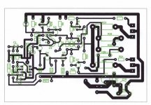
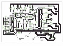
The Pcb's for the original and if anyone is interested see post 283 in the "Post your solid state pictures here" forum, were real one offs made to fit the "metalwork" I had available.
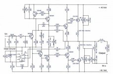
I have only recently started to get to grips with a PCB package and another DIY member expressed an interest in this amp, asking if I had any design available. All I can offer is an "untested" layout which I will post here.
Regards Karl
Above all else I wanted an amp that was "musical" and this amp has certainly achieved this. Now 95 % of my discs sound wonderful, the real musical worth of the performance comes across. You can listen for hours on end, and I do sometimes, the sound is absolutely captivating.
It's like I say, you can walk into a High Street and someone is playing a violin, it's a poor instrument and being played to an average standard and yet there is that "real" quality to the sound, something very few audio systems can capture and achieve.
The design owes much to the thinking of the late John Linsley Hood. I went back to a single ended input stage for a couple of reasons, firstly, it's more much more docile than the the normal long tailed pair, much less critical in layout, compensation etc ( that's not an excuse by the way ) and finally the distortion produced is mainly even harmonic, which is much more pleasing to the ear.
I mentioned in another thread that I believe the way an amp responds to "real speakers " as a load is crucial, not just the obvious things like overshoot and stability, but how it reacts to what is in effect a generator hung on the output. Each speaker is a pretty good microphone as well and feeds "back" into the amp. How the amp and negative feedback loop responds to this I believe is crucial. Connect a large speaker to an amp and flick the cone with your finger and look at the feedback signal in the amp.
So much for a "high" damping factor.
As to absolute performance figures (THD TIM etc), I am afraid I do not have the equipment to measure to low very levels.
The Pcb's for the original and if anyone is interested see post 283 in the "Post your solid state pictures here" forum, were real one offs made to fit the "metalwork" I had available.
I have only recently started to get to grips with a PCB package and another DIY member expressed an interest in this amp, asking if I had any design available. All I can offer is an "untested" layout which I will post here.
Regards Karl
Hi Mooly,
A few questions and an observation.
Why use 22k for R1? is this to suit a specific pre-amp or does the amp sound better with this comparatively low value?
Why use C3 to Block DC in the NFB loop and use a DC servo?
Any advantage in adding <=10r in parallel to the output inductor?
The location of C7 from voltage amp output to input's emitter shows the "British" heritage of this amp rather than wrapping Miller comp cap around Q4/5
Hi Andrew,
R1, I use a 10K volume control in front of this, so there's no real reason for it being so low, it's just the value that I settled on during development, it works well, although it will alter the law of the pot somewhat.
C3, Essential, the input is single ended and the normal quiescent base volts on Q1 is about minus 7, the emmiter of course at about -6.4 volts. Think of it as a single rail amp, where you would set the "midpoint" voltage on the outputs with a pot. The feedback arm would have to be A.C. coupled here, and this is the same. A pity though, I agree.
10ohm in parallel with inductor, well spotted, yes it has one actually in real life, it's funny how you can look at something a million times and not see it. This is my first attempt using "Diptrace" and I copied it over from the original hand drawn circuit. I shall amend it, thanks.
C7, around Q4/Q5 , Erm they are not FET's are they, I talked to them, I asked them, "what would you prefer"----sorry, Andrew knows where that's come from. I found it gave good, predictable results, so I just stuck to a simple single pole compensation scheme that incorporated the VAS but was not wrapped around the drivers and outputs, hopefully to help with any TIM but I can't measure this. It does the job and does it brilliantly.
Thanks for the interest.
Karl
- Status
- This old topic is closed. If you want to reopen this topic, contact a moderator using the "Report Post" button.
- Home
- Amplifiers
- Solid State
- clean, wrm, sweet sound amp CLass A