Hi Gareth,
The transparancies I use are from www.cpc.co.uk, they do all you need, but don't walk before you can run. They are called Jetstar, and they say for Epson printers but am sure must work in any.
Look at www.megauk.com probably a better bet actually and lots of info as well. Before you take the plunge, design a simple board as I suggested, and print on paper, see it all looks O.K.
You have to get used to diptrace, moving and rotating parts, printing the layout with and without component references etc. A boards no good with all the printing on it, shorts everything out") . It just needs practice, if I can do it anyone can.
. It just needs practice, if I can do it anyone can.
So there you go, you pick a simple circuit, post it here, and design the board, an hour tops.
You can do this.
The transparancies I use are from www.cpc.co.uk, they do all you need, but don't walk before you can run. They are called Jetstar, and they say for Epson printers but am sure must work in any.
Look at www.megauk.com probably a better bet actually and lots of info as well. Before you take the plunge, design a simple board as I suggested, and print on paper, see it all looks O.K.
You have to get used to diptrace, moving and rotating parts, printing the layout with and without component references etc. A boards no good with all the printing on it, shorts everything out
. It just needs practice, if I can do it anyone can.So there you go, you pick a simple circuit, post it here, and design the board, an hour tops.
You can do this.
Mooly said:Hi Gareth,
The transparancies I use are from www.cpc.co.uk, they do all you need, but don't walk before you can run. They are called Jetstar, and they say for Epson printers but am sure must work in any.
Look at www.megauk.com probably a better bet actually and lots of info as well. Before you take the plunge, design a simple board as I suggested, and print on paper, see it all looks O.K.
You have to get used to diptrace, moving and rotating parts, printing the layout with and without component references etc. A boards no good with all the printing on it, shorts everything out
So there you go, you pick a simple circuit, post it here, and design the board, an hour tops.
You can do this.
Cheers, advice taken! I think I will start with a clock design for my 63, seems simple enough to me, then I'll post the design, wait for any comments and suggestions then away to go, no? Or will I wipe my CD out....anyway only one way to find out.
Gareth
Edit..what am I talking about, let's take it easy as you said. A simple single op-amp with a couple of resitors and caps...post it, get suggestions then away to go. You're completely right, learn to walk first.
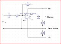
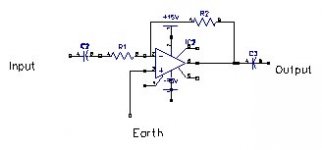
Mooly said:Right, while we are about it then, why not also draw the schematic with Diptrace and post that first. I will do one as well if I have time, we will compare notes. I will do a 741 OpAmp, inverting with coupling caps.
Regards Karl
Ok Karl I'l give it a try but be prepared I may take a little time if that's alright with you.
Gareth
gareth said:
Good thinking..what do you mean by a double-thick transparency though?
Thanks
Gareth
As others have found out from the same bad experience - it never prints out dark enough no matter how good your printer is. Stack two and it's dark enough. In the olden days of the negative resist process and actual photo negatives, they *were* dark enough.
wg_ski said:
As others have found out from the same bad experience - it never prints out dark enough no matter how good your printer is. Stack two and it's dark enough. In the olden days of the negative resist process and actual photo negatives, they *were* dark enough.
Ok thanks, so if I print two copies and stack them that will block out any UV. OK. Would I still need to do this even if I have a Epson photo printer??
Thanks
Gareth
Right then Karl, I have attempted this and I hope you can point out where I've gone wrong.
I have downloaded the tutorial but have not had the chance to read it yet as I have been in work all day. I had to convert the .bmp in Photoshop for instance.
I have downloaded the tutorial but have not had the chance to read it yet as I have been in work all day. I had to convert the .bmp in Photoshop for instance.
Attachments
It's OK actually, This will fun, switching between screens. To draw a line such as my 9volt click "place wire" it's 12 symbols in from right on toolbar. I am doing this now ! Move cursor over where you want line to begin or connect to, left click and "draw" If its just an open ended lead such as power drag it to where you want , right click, and select enter.
el`Ol said:http://www.buscher-endstufen.de
have kits for SE MosFet amps up to 50W @4Ohm.
I don´t have first hand information about them, but they are said to be very sensitive to the resistor type and out of the box they are rather "fast" than "sweet" due to the metal film resistors. I just pass this over, I don´t believe that too much myself.
Am I the only one who notice the uncanny similarity to the Aleph amplifiers?
When you have dragged a part from the left side to work with, right click it, open "properties" and you can alter text etc for that part, go to "markings and you can decide where text appears, top of component/left/right etc. You have to really play with this, try rotaing the parts as well.
Thats brilliant, you have got to play around with this.
Heres one we made earlier
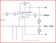
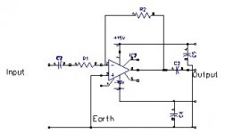
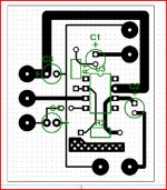
I am going to have to go now, but this PCB is as bad as it get's Again play, I have changed pad sizes, track widths etc and added a nice "copper pour". All this is done straight onto the pcb program. So you will have to find your bits again in the library.
Heres one we made earlier
I am going to have to go now, but this PCB is as bad as it get's
Again play, I have changed pad sizes, track widths etc and added a nice "copper pour". All this is done straight onto the pcb program. So you will have to find your bits again in the library.Attachments
Sorry if this is obvious, click file, and save as etc , give it a name.
Next time you open schematic select, "file" and open recent -- any items you were working on will be there just as you left them when you saved them. If you see what I mean. Play Play and Play, use the normal "edit" on the toolbar to undo anything and keep "refreshing" save as you work.
Must go now, see how you get on
Regards Karl
Next time you open schematic select, "file" and open recent -- any items you were working on will be there just as you left them when you saved them. If you see what I mean.
Play Play and Play, use the normal "edit" on the toolbar to undo anything and keep "refreshing" save as you work.Must go now, see how you get on
Regards Karl
space2000 said:...which can produce sweet, wrm and clean sound.
sweet sound = SE = even order harmonics dominated, h2 up to 10% acceptable
detailed sound = PP = odd --||-- h3
Hi Rellum,
It should be fine on 36 volt rails, I used much lower than that during design.
I know from past experience that it is easy to change something without evaluating it first and then seeing an unexpected problem appear. The BUZ's are I believe "double die" types, in effect two transistors in the one package. That's why they are double the current rating of the 2SK/J. The gate capacitance is going to be higher (double), but I don't think this will cause a problem at all. R27, yes you can drop that, the TLO71 only needs a couple of milliamps + a couple through the zener. 5.6 K 0.6 watt should be fine, R6 to say 82 K with R4 left at 22K. Might be worth dropping R18 and R21 to perhaps 180 ohm becase of the larger gate capacitance, but these are all things you can tweak. And keep these as close to the gates as posible ( very important ).
Regards Karl
- Status
- This old topic is closed. If you want to reopen this topic, contact a moderator using the "Report Post" button.
- Home
- Amplifiers
- Solid State
- clean, wrm, sweet sound amp CLass A