guys - i have a really big problem (in my point of view)...
i draw in the simulator a schematic and there it is working perfectly.... but when i made a pcb board and everything i found out that i can't bias the amplifier..... i have no bias current flowing threw the output devices....
so i started measuring few spots and i found out that i have some current flowing threw the bias circuitry but i do not have any current flowing threw the driver transistors....
can somebody please help me and tell me what is going on and what should i look to solve the problem....the pcb seems to be o.k. (but still it can be faulty and i can't find the problem there)
i am working arround this problem for two days now and i am really crazy and sad now because of it....
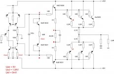
the VAS, driver, and bias circuitry with some voltages looks like this....
i draw in the simulator a schematic and there it is working perfectly.... but when i made a pcb board and everything i found out that i can't bias the amplifier..... i have no bias current flowing threw the output devices....
so i started measuring few spots and i found out that i have some current flowing threw the bias circuitry but i do not have any current flowing threw the driver transistors....
can somebody please help me and tell me what is going on and what should i look to solve the problem....the pcb seems to be o.k. (but still it can be faulty and i can't find the problem there)
i am working arround this problem for two days now and i am really crazy and sad now because of it....
the VAS, driver, and bias circuitry with some voltages looks like this....
Attachments
Hi,
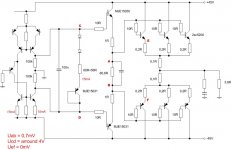
Not enough bias voltage, Vcd needs to be around 2.9V for standing current.
To turn your output stage on you need at least 4 diode voltage drops,
plus the expected voltage drop across the emitter resistors at the
nominal bias current.
See : http://www.dself.dsl.pipex.com/ampins/dipa/dipa.htm
") /sreten.
/sreten.
Not enough bias voltage, Vcd needs to be around 2.9V for standing current.
To turn your output stage on you need at least 4 diode voltage drops,
plus the expected voltage drop across the emitter resistors at the
nominal bias current.
See : http://www.dself.dsl.pipex.com/ampins/dipa/dipa.htm
/sreten.i tought that this is the reason but what is bothering me is that in simulator it is working with those values i have used (and that are on the sch in the first post of this thread) ....
how can it be that in simulator it is working with used values of resistors and in real life the values are a lot bigger ????
can someone explain this to me????
(i know that simulator is a simulator and real life is a real life) but i am very scared not to burn anything....
is it really that high i have to go - 4 diodes and a resistor of lets say 68R???
Hi,
Vab should not be zero. If you look at the loop for the drivers with
Vcd = ~ 2.0V, Vab should be ~ 0.6V, which is nowhere enough for
a standing current in the output stage. Vab needs to be at least
two diode drops. Use one transistor as an amplified diode for bias.
/sreten.
Vab should not be zero. If you look at the loop for the drivers with
Vcd = ~ 2.0V, Vab should be ~ 0.6V, which is nowhere enough for
a standing current in the output stage. Vab needs to be at least
two diode drops. Use one transistor as an amplified diode for bias.
/sreten.o.k. - i will ad here one diode and than two diodes to see what will happen
i hope everything will be o.k. - i was not sure what is happening since in the sim everything was working fine with two transistor diodes and that resistor... and in real life this is not so....
oh man!
o.k. - thank You
very much...
i hope everything will be o.k. - i was not sure what is happening since in the sim everything was working fine with two transistor diodes and that resistor... and in real life this is not so....
oh man!
o.k. - thank You
very much...
thank you for your answer - in other words - schematic like this should work.... o.k. i will check the resistor connection (i have done that but i will do it again).... also i will check Vbe of the driver transistors and than i will come back...
thank You for the reply again...
thank You for the reply again...
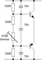
Before you begin to attach power transistors, its better to obtain Vcd about 2.4-2.7 V. Circuit with resistor is bad, because bias of output transistors will depend on driver bias. Use bias schematic like this. But change upper resistor nominal, it’s for follower on 3 transistor on side.
Attachments
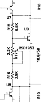
sunrise said:VBE is 17.6 and 13.57V on the driver transistors...that is Vca= 17.6V and Vbd= 13.57V....
emitter resistor and base resistors of the drivers are connected o.k.
Or transistors are bad or mounting errors
Vac= -17.57V.....
Vbd=-13.57V.....
(plus of the multimeter on the "a" and on the "b" spot)
the interesting thing is that these values are slowly droping.....when i finished the meauring (about a minute after the turn on) the value drop down to 11V and 8V..... how about that...???
Vbd=-13.57V.....
(plus of the multimeter on the "a" and on the "b" spot)
the interesting thing is that these values are slowly droping.....when i finished the meauring (about a minute after the turn on) the value drop down to 11V and 8V..... how about that...???
i am sure about the values...
multimeter....negative to ground and measured values like this:
Va=0,46V
Vb=0,46V
Vc=18V
Vd=14V
Ve=1.6mV
Vf=1.6mV
then i measured folowing values:
Vab= 0V where negative of the multimeter was on the "b", Vcd= 4V (negative on "d"), Vac= -17,56V (negative on "c"), Vbd= -13,58V (negative on "d")
multimeter....negative to ground and measured values like this:
Va=0,46V
Vb=0,46V
Vc=18V
Vd=14V
Ve=1.6mV
Vf=1.6mV
then i measured folowing values:
Vab= 0V where negative of the multimeter was on the "b", Vcd= 4V (negative on "d"), Vac= -17,56V (negative on "c"), Vbd= -13,58V (negative on "d")
- Status
- This old topic is closed. If you want to reopen this topic, contact a moderator using the "Report Post" button.
- Home
- Amplifiers
- Solid State
- a problem - no bias current