A beautiful day here - 27*C, a great spring day. I did some yardwork (raking up dog poop) and did a few other things around the backyard.
I also found time to finish up some of the parts for this amp. I started with the base, which early last week I added the stainless steel bands to the feet. After masking out the SS, I brought it out and painted it a nice even coat of flat black. This is done now, ready for the power supply components.
I then finished the front panel illuminated switch. I looked for these to buy, but wow, are they expensive. I have better things to spend $60.00 on, so I made my own. This is the second one I've built. The first is in my new PC case that I did over the long, cold winter.
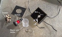
It's not as difficult as it may seem. The problem came with what to make the lit up ring out of, and how to illuminate it. I used a standard clear plastic pill bottle, that I carefully cut off, smoothed and polished. A package of two push button switches from Radio Shack and a few other items (used circuit board, LED's, etc.) and it's done. See the pic below, as it shows everything. The button itself is a piece of 1/4" hardboard cut to fit inside the pill bottle.
I also found time to finish up some of the parts for this amp. I started with the base, which early last week I added the stainless steel bands to the feet. After masking out the SS, I brought it out and painted it a nice even coat of flat black. This is done now, ready for the power supply components.
I then finished the front panel illuminated switch. I looked for these to buy, but wow, are they expensive. I have better things to spend $60.00 on, so I made my own. This is the second one I've built. The first is in my new PC case that I did over the long, cold winter.
It's not as difficult as it may seem. The problem came with what to make the lit up ring out of, and how to illuminate it. I used a standard clear plastic pill bottle, that I carefully cut off, smoothed and polished. A package of two push button switches from Radio Shack and a few other items (used circuit board, LED's, etc.) and it's done. See the pic below, as it shows everything. The button itself is a piece of 1/4" hardboard cut to fit inside the pill bottle.
Attachments
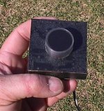
Here is how the switch looks installed. Sitting on the sub woofer it will eventually drive the heck out of.
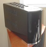
Indeed, except for further polishing and waxing of the case, this is how the final amp will look (if I ever get the insides done") ).
).
I need to clean the polishing compound out of the ventilation gills (the white stuff).
Indeed, except for further polishing and waxing of the case, this is how the final amp will look (if I ever get the insides done
).I need to clean the polishing compound out of the ventilation gills (the white stuff).
Attachments
Dr.EM said:Looks great! Please finish the insides
Thanks, I'm working on it.
It will be some time before it is finished. Never meant for this to be a quick project. The complexity is higher than I expected, with the support circuitry out-weighing the amp circuitry.
I'm making my own boards and it's fast and convenient to do this, but after a couple of days they don't look so good anymore. The copper turns a mottled brown and it's hard to take pride is your hard work when it looks like krap.
So, I searched for something to use as solder mask and I found a thread here where a member (can't recall who) said that the Testors model paint in a spray can works well. Fine, I thought, I'll pick some up.
Stopped at the local Walmart on the way home from work to get it. "Sorry, we don't sell models anymore"
Wow. What's happening? It's been a while since I put together a model (briefly got into it about 5 years ago), but when I did there was a vast selection at that same Walmart. Where's the outlet for the DIY spirit in the young of today? A shame really.
Anyhow, I go to a couple other places and they don't have it either. I finally go to Canadian Tire ( used to be my favourite retail place to go, but lately that's changed as they turn into more of the typical junk store). They had a toy department before, but not now.
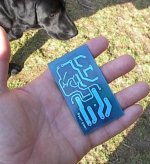
I have a look in the automotive paint isle, and find a product called "Metalcast Anodized surface colour system". Spray can. It comes in blue, red and green. It's meant to be sprayed on bare aluminum valve covers or manifolds to make them look dyed anodized. Says on the can that it resists heat and chemical attack, so I pick up a can of green and blue to try.
Wow, is this stuff great! just like the real thing. I sprayed it on and let it dry, then put the heatgun on it and this stuff held up. I even tried to iron on the laser transfer print for the silkscreen and that worked great too.
Highly recommended.

Attachments
EWorkshop1708 said:VERY nice!
I wonder if you can spray that metallic paint on heatsinks?
Well it's meant for raw or anodized aluminum so yeah, it should work fine. Colours are limited though. See the brackets I made for the smoothing caps below that I sprayed the green on. These are sheet metal though, and not aluminum.
Dr.EM said:That looks great. Do you remove the spray from pads you need to solder to with acetone or sanding, or would you mask them off before spraying? Your etching looks really clean, my etching attempts have been epic failures!
Thanks again. I believe the fastest and easiest way to deal with the pads is to just scrap the coating off with the tip of a sharp knife. Masking and then peeling that off would take at least twice as long.
I love making these boards, but I'm sure that will wear off after a bit. To get good results you need to have the right paper and printer. Patience and following the directions exactly will get you there.
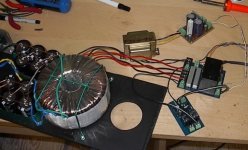
I made some good progress today on the power supply. After considering the best way to mount the caps, I decided to use two brackets, to get a better fit around the transformer. As shown in the picture below, they turned out pretty good.
I also made a hold down strap for the toroid, that keeps the centre open for ventilation. This is not in the picture, as I did that later.
I also brought it in and wired it up. I used an aluminum angle to mount the two bridge rects on.
With it done, I connected a temporary power cord, crossed my fingers and turned it on. No lightning bolts! No fire!
I read +/-72.6VDC to ground. Excellent.
Attachments

I have completed the power control circuitry. This includes the soft start, the low voltage power supply and the main relay board.
The low voltage power supply board was finished earlier (therefore NOT my sexy blue solder mask) and provides +/-15VDC for the Linkwitz transform and 24VDC for the main power relay and speaker relay.
I used Rod Elliot's soft start, with a change. I made it with 2 relays, one for each primary on the toroid. This (I assume) lessens the load on the relays contacts. I used 125VAC, 7A miniature relays for this. This board also splits the 24VDC to +/-12VDC for the circuit and these relays.
The main relay board has the relay (duh!), the line fuses (one for the low voltage and one for the main supply), the 2 soft start ballast resistors (I used 20 ohm, 10W here), and a bunch of terminal blocks for wire routing.
Hooked everything up and it works beautifully.
Just need to find space for all of this and try to get it all mounted.
Getting closer though.
Attachments
Back to the amp itself. I have a new schematic ready, with just a few changes.
I will be starting the tedious task of doing yet another board layout to try this one. I'm feeling confidence about it though, given the previous success.
I've stripped and throw away the last board.
I will be starting the tedious task of doing yet another board layout to try this one. I'm feeling confidence about it though, given the previous success.
I've stripped and throw away the last board.
Attachments
Hi there MJ,
Just a few comments after looking over some of your posts....
nice case work !! it looks great !!
also nice board work !! blue solder mask looks cool...
Just wondering why you used ZTX696B input rather than an MPSA42 / 2SC1845 or something similar ?
what is the lowest impedance you lan to use with this one ?
-Dan
danieljw said:Hi there MJ,
Just a few comments after looking over some of your posts....
nice case work !! it looks great !!
also nice board work !! blue solder mask looks cool...
Just wondering why you used ZTX696B input rather than an MPSA42 / 2SC1845 or something similar ?
what is the lowest impedance you lan to use with this one ?
-Dan
Hi again Dan,
Thanks, I have my talents and building things is one of those. I'll need about a billion years to catch up with the electronic side of things...

The solder mask paint sticks like crazy to the board itself , but is easily scratched off of the clean copper. I wonder if I tinned the traces first before painting, would it stick better?
I used the ZTX for it's high gain. I heard the input stage should have high gain transistors, so I used those. My old version used the MPSA42, and didn't show any problems. At $1.75 a piece, the ZTX weren't cheap, and would probably be well worth it in a full range amp.
I have already driven a 1.5 ohm load to ~750 watts, and that was with the CFP output, so a little oscillation was evident. I am hopeful that with the change to Darlington, it will easily drive 2 ohms stable. Fingers crossed.
EWorkshop1708 said:I'd highly recommend raising C4 from 2.2uf to 10uf since it's a sub amp.
As a matter of fact, I just got some 10uF bipolar in my latest order from Digikey especially for that purpose.
See anything else? Any suggestions for improvement or maybe one of my stupid mistakes?
EWorkshop1708 said:You could still try some compensation caps for your U2 and U4 drivers to reduce the chances of oscillation.
Added. Like this?
Attachments
danieljw said:My two cents on the two caps you just added to reduce oscillation
I recently used 150pF with good results in similar situation.
-Dan
I just copied C3 and stuck them in without changing the values. These will be left open unless they need to be used. At least this way, I won't need to tack them on the bottom of the board.
I ordered some 36 ohm 10W resistors to build another dummy load, but now I'm uncertain if it would handle the power, even if it is fully submerged in cold water. It would take 18 in parallel to get 2 ohms. That's only 180 watts. Am I seeing this correctly, or would this handle as much as 1000 watts if it's kept cool?
I don't want to waste my time putting these together if they are just going to blow.
- Status
- This old topic is closed. If you want to reopen this topic, contact a moderator using the "Report Post" button.
- Home
- Amplifiers
- Solid State
- 1000 Watt Sub Amp: Design / Build