Just FYI:
In my experience B&Ws can be improved greatly in the midrange by adding some decent stuffing behind the mid driver. Usually there are a few wisps of white poly foam, whereas pure wool would be the way to go here. Extra braces are also good.
Thanks... I'm really happy with them sound wise, chosen after a lot of listening and comparisons.
It is possible to greatly improve rail efficiency (output swing) of this amp by making CFP an over-unity gain stage with a gain of about 1.15-1.25. Easily done by adding two 1.5k 1W resistors from emitters of Q6/Q7 to the ground. Such small gain will have negligible effect on both THD and phase margin.
It is particularly suitable for this amp since Q6/Q7 run very little current, thus power dissipation in Q6/Q7 emitter dividers (for over-unity CFP gain) is small.
There are many possible changes/alterations that can be considered but the design as presented is fully developed and meets all it's objectives.
By all means experiment if you wish, but don't lose sight of the fact that the amp may well perform or sound very different if any changes are made.
Any such changes need to be fully evaluated in both listening tests and measurement.
thanks for interest
")
Hi Jay,
Speakers I use are these, which have a 3 ohm minimum impedance.
View the 703 at Bowers & Wilkins - The World's leading Hi Fi Brand
View the 703 specifications at Bowers & Wilkins - The World's leading Hi Fi and Home Theatre Brand
The BMW is suitable for the mosfet. If it was okay with the Celestion (6in?) then I'm fine
Good then. I haven't found a preamp that I like to use. But I haven't built the Pass' B1 buffer. Will build that before building my own.The amp will work just fine without a preamp if used with a CD player etc. Just use a 10 or 22k pot as a volume control. The feedback factor is low, and corresponding input sensitivity high. 22k and 470 ohm for the feedback equates to a voltage gain of 48, or 33db if you prefer.
Why it has to be a JFET input? Does high input impedance matter? I have checked the specs of some of my opamps. LF356 is indeed a JFET-input but it's specification is much worse than TL071 in audio or in this DC operation, and also worse than OP07 (or OP05) which are bjt-input. OP07 is better than TL071 or LF356 in noise performance, CMMR and PSRR. TL071 is superior in slew rate only, which I think is irrelevant. So, why not better use OP07? (OP05 slightly worse in CMMR but better offset drift over time and temperature)The DC servo. First it must be a FET opamp that you use, not a bjt. The power supply for opamp only has to be sufficient to provide the bias for the input transistor, so -12 volts is perfect as the output of the opamp will be around -5 from memory. If you use an IC that can't work with the + input (pin 3) tied to the positive supply (pin 7) when running on a single supply then you will have to provide a split supply for it, in other words -/+12 volts. The TL071 and single zener seemed the most elegant engineering solution. The LF356 should also work correctly I suspect. Remember the opamp isn't in the audio path as such and it's AC characteristics are not important... apart from the high input currents a 741 would be just as good here. The opamp won't affect the sonics. A separate PSU for it is not required.
You're right, I don't need a separate PSU (I was worrying its effect to the signal). I will use double diode as attached.
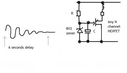
But it will be split supply, so twice of that? What is the effect of omitting the delay circuit?What is ESSENTIAL for a finished amp is the relay delay at power up as the servo takes a few seconds to settle. This can be a really simple design, little more than a power transistor with an RC network on the base to give the delay. As simple as that.
Ups, you mean the output will not be at ground level? Where will you put the mentioned delay network? Near power button (power supply)? Do you mean to delay the supply to the coil of on-off relay?
Attachments
Last edited:
Just FYI:
In my experience B&Ws can be improved greatly in the midrange by adding some decent stuffing behind the mid driver. Usually there are a few wisps of white poly foam, whereas pure wool would be the way to go here. Extra braces are also good.
Hi Globulator, I believe your experiences are related to 2-way BNWs. Mooly's are 3-way, and a good one. Braces might not be necessary because sometimes box sound is good
Hi Jay,
The opamp for any servo needs to have low (preferably "zero") input bias current to enable the integrator cap to be kept low in value (the 0.1uf... small, available in high quality types, inexpensive) and the resistor feeding it high (the 1m). The input currents of a bjt device are significant and would cause a large DC offset due to the bias current "developing" a volt drop across the 1 meg resistor.
FET devices have essentially zero DC bias current.
The TL071 holds the output offset to well under 1mv without any trimming or fuss, it's perfect for the job.
You could use a 741 or a 5534 or many other types and reduce the 1 meg to say 10k to minimise offset due to the input current, but then the cap would have to be scaled up accordingly... and a 10uf poly cap isn't cheap or small.
The servo causes the amp to produce a "damped" low frequency sinewave due to the action of the servo correcting the output and the time constants within the amp itself (feedback return cap etc) like this, so this is why the delay is required. To me any amp should be totally silent on power up. If you arrange a separate "rail" for the delay using a half wave rectifier and cap from one of the windings on the tranny and center tap then by choosing a "low" value for the reservoir cap the dalay circuit can be made to drop out quickly before the main rails to the amp collapse.
The relay is used to isolate the speakers. Choose R and C to give around 6 seconds delay.
Attachments
Hi Jay,
The opamp for any servo needs to have low (preferably "zero") input bias current to enable the integrator cap to be kept low in value (the 0.1uf... small, available in high quality types, inexpensive) and the resistor feeding it high (the 1m). The input currents of a bjt device are significant and would cause a large DC offset due to the bias current "developing" a volt drop across the 1 meg resistor.
FET devices have essentially zero DC bias current.
The TL071 holds the output offset to well under 1mv without any trimming or fuss, it's perfect for the job.
You could use a 741 or a 5534 or many other types and reduce the 1 meg to say 10k to minimise offset due to the input current, but then the cap would have to be scaled up accordingly... and a 10uf poly cap isn't cheap or small.
Okay thanks I got the reasoning. Typical input bias for OP07 is 1.2nA at room temperature. I guess it is low enough, compensated by its low input offset voltage (at least 100x lower than TL071). Later I will check the voltage rating of my smallish Black Gate NX capacitor. The RC is to create a pole for LPF right? What is the max frequency so to isolate from audio frequency (AC), 10Hz? But there's no resistor in parallel with the cap hmmm
I will check my other opamp then... OPA627... 0.9nA@25deg. TL071 is 0.009nA@25deg
Oh well, whatever, my expertise is not to calculate but to plug and play and to listen Only just spotted this.
http://www.diyaudio.com/forums/solid-state/168855-moolys-amp-safe-build.html
Whaddya mean "Is it safe to build" ?
Just get it built Jay
Opamp integrators don't have a resistor in parallel with the cap... maybe you are thinking of "non inverting" type that have an RC network "before" the opamp.
Audio Power Amplifier Design Handbook - Google Books
Edit... this is good, an "interactive" web based integrator.
http://www.wisc-online.com/objects/ViewObject.aspx?ID=SSE5303
Last edited:
Safe for the speaker in case of failuresOnly just spotted this.
http://www.diyaudio.com/forums/solid-state/168855-moolys-amp-safe-build.html
Whaddya mean "Is it safe to build" ?
Sure. Planning for a permanent build I have wasted much time for preparing the housingJust get it built Jay
It's hard for me just to pick transistors before measuring them Also I'm not yet decided whether I will prepare for paralleled mosfets or not (I think not).Do you think going double transformers (dual mono) would be any better?
On each supply rail (on-board) I will put Black Gate F 680uF + Elna Cerafine 220uF, but I'm not sure whether I will also put a Solen MKP (From experience I like the Solen MKP in the supply rail).
For main capacitance, I have plenty of bad quality audio caps. Good quality ones only in pair (2 pieces for each type/brand). That's why I prefer a single supply so I can use only two caps. I have two Nippon Chemi-con CE 8200/85. It is not audio grade but I like it. I think too big of "capacitance" will degrade the sound. Too bad many people like the better ripple smoothing effect and the bass performance of big caps
Yes, I was thinking about your statement that it doesn't work in audio frequency which I still doubt. So I thought there must be a mean in the opamp circuit to calculate the frequency cut-off.Opamp integrators don't have a resistor in parallel with the cap... maybe you are thinking of "non inverting" type that have an RC network "before" the opamp.
Yes, that is good. My (downloaded) reference is the National AN-20 pdf. But I haven't read it again.
I will measure the 2n5551/2n5401....
No direct coupled amp is safe for speakers if it fails, and almost all DC offset protection circuitry has a finite delay when it does operate, the integrator network (in the offset protection circuit, not the amp) for one thing, and the mechanical delay of the relay for another. It all adds up and the speaker may see the full rail voltage for 10's of milliseconds. Actually isolating a speaker under such conditions is fraught with problems too. The "arc" that a large inductive load such as a woofer wil draw when connected across DC and then switched off is huge... most relays won't survive that, the contacts just weld together.
How much of a problem is this ?
For a correctly designed amp, correctly built it just shouldn't happen. Semiconductors are supremely reliable, the reasons why they fail are usually due to incorrect use, running them beyond their limits etc. Or "customer abuse, shorting the outputs etc.
And the other issue of course is how well built the amp is. On a proper PCB correctly soldered, neatly wired, then there is no possibility of unintentional shorts etc.
And... another point... the lateral FET's really are robust. There is no secondary breakdown like bjt's and even when abused they seem to survive.
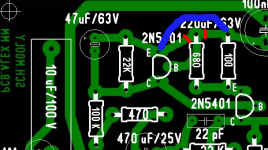
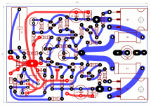
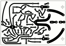
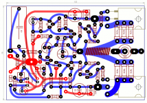
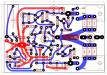
Are you designing your own PCB ? If so make sure you keep the decoupling cap ground returns out of the main signal ground.
True dual mono construction theoretically is better, the two channels are 100% electrically isolated. Downsides are housing the two trannys, doubling up PSU components, and if the two are in one case then weight, transformer interaction/layout etc.
I would use a single and get the wiring correct.
Larger caps=better bass. Not exactly. I've been there before, and that's not how it works
This thread wandered about but have a look at posts #111
http://www.diyaudio.com/forums/soli...subjective-objective-views-6.html#post2204105
Also extremely large caps cause the charging currents in the bridge and transformer to become higher as the conduction angle of the bridge is reduced. In other words the same energy has to be put back, but the larger caps maintain the voltage$ more between each half cycle, so the actually time the bridge conducts is less, but the current is much higher.
The integrator. This is difficult to analyse simply. The reason why is that the amp has a number of factors affecting the extreme low frequency response.
There is the input coupling cap. There is the cap in the feedback return.
At this point you could just set a fixed bias for the input stage and not use a servo... the downside would be unacceptable drift in the operating point, the DC offset at the output would wander with temperature.
The "servo" actually provides this bias voltage, the action of the integrator "removes" the audio and simply provides an "average" DC voltage that when the "loop is closed" holds the output at zero volts. All that appears at the output of the opamp is DC.
It's a standard well known technique, nothing new.
As the frequency decreases there comes a point where the integrator becomes less effective, and the very low frequecy output starts to appear at the opamp output.
Where it gets complicated is that this also interacts with the time constants of the input cap, and also the feedback cap. The result is that as the frequency reduces, there is a sudden point at which the output from the amp increases, then the response falls away.
All this happens way below the audio range though. You could increase the value of the integrator cap or resistor... the downside of this is a longer settling time from switch on.
I found the values used a very good compromise.
How much of a problem is this ?
For a correctly designed amp, correctly built it just shouldn't happen. Semiconductors are supremely reliable, the reasons why they fail are usually due to incorrect use, running them beyond their limits etc. Or "customer abuse, shorting the outputs etc.
And the other issue of course is how well built the amp is. On a proper PCB correctly soldered, neatly wired, then there is no possibility of unintentional shorts etc.
And... another point... the lateral FET's really are robust. There is no secondary breakdown like bjt's and even when abused they seem to survive.
Are you designing your own PCB ? If so make sure you keep the decoupling cap ground returns out of the main signal ground.
True dual mono construction theoretically is better, the two channels are 100% electrically isolated. Downsides are housing the two trannys, doubling up PSU components, and if the two are in one case then weight, transformer interaction/layout etc.
I would use a single and get the wiring correct.
Larger caps=better bass. Not exactly. I've been there before, and that's not how it works
This thread wandered about but have a look at posts #111
http://www.diyaudio.com/forums/soli...subjective-objective-views-6.html#post2204105
Also extremely large caps cause the charging currents in the bridge and transformer to become higher as the conduction angle of the bridge is reduced. In other words the same energy has to be put back, but the larger caps maintain the voltage$ more between each half cycle, so the actually time the bridge conducts is less, but the current is much higher.
The integrator. This is difficult to analyse simply. The reason why is that the amp has a number of factors affecting the extreme low frequency response.
There is the input coupling cap. There is the cap in the feedback return.
At this point you could just set a fixed bias for the input stage and not use a servo... the downside would be unacceptable drift in the operating point, the DC offset at the output would wander with temperature.
The "servo" actually provides this bias voltage, the action of the integrator "removes" the audio and simply provides an "average" DC voltage that when the "loop is closed" holds the output at zero volts. All that appears at the output of the opamp is DC.
It's a standard well known technique, nothing new.
As the frequency decreases there comes a point where the integrator becomes less effective, and the very low frequecy output starts to appear at the opamp output.
Where it gets complicated is that this also interacts with the time constants of the input cap, and also the feedback cap. The result is that as the frequency reduces, there is a sudden point at which the output from the amp increases, then the response falls away.
All this happens way below the audio range though. You could increase the value of the integrator cap or resistor... the downside of this is a longer settling time from switch on.
I found the values used a very good compromise.
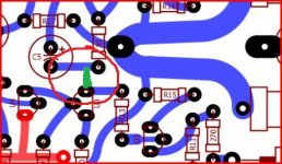
This is a error?
.
Attachments


- Home
- Amplifiers
- Solid State
- My MOSFET amplifier designed for music