Hi Francis,
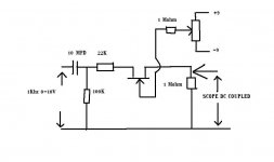
Try this-- it will give you a feel for what happens. If you apply say 4 volts peak to peak and take the gate to 0 volts it will conduct. There will be NO dc offset across the output-just the signal. Now take the gate higher and at around 0.3 volts a DC shift will appear as the gate channel begins to conduct. You need the gates close to this value to minimize their on resistance. That 0.2 volts makes quite a difference. Change the 22 K and 1 meg for say 100 ohm ( I am guessing these values but this is what I did ) so the resistance of the FET affects the output. The voltage now across the 100 ohm output will rise significantly as the gate goes from zero to 0.3 volts. Put the original values back and now swing the gate negative. To "block" 4 volts you need -4 on he gate, to block 6 volts you need -6 and so on.
In the inverting configuration I use there is no signal ( only a few millivolt ) across the FET, so this isn't such a problem anyway but do try it, it makes it easier to understand what happens.
Again going off memory I think the resistance of the FET was around 70 to 80 ohms at zero volts gate, and fell to below 30 ohms at 0.2 volts.
Another gem of information") Have you ever wondered how to identify the source and drain. You will find it dosn't matter which way round you put the FET's. And that's official -- I asked Bob Pease at National Semiconductor, as it was something that always puzzled me. Thanks again Bob.
Have you ever wondered how to identify the source and drain. You will find it dosn't matter which way round you put the FET's. And that's official -- I asked Bob Pease at National Semiconductor, as it was something that always puzzled me. Thanks again Bob.
Try this-- it will give you a feel for what happens. If you apply say 4 volts peak to peak and take the gate to 0 volts it will conduct. There will be NO dc offset across the output-just the signal. Now take the gate higher and at around 0.3 volts a DC shift will appear as the gate channel begins to conduct. You need the gates close to this value to minimize their on resistance. That 0.2 volts makes quite a difference. Change the 22 K and 1 meg for say 100 ohm ( I am guessing these values but this is what I did ) so the resistance of the FET affects the output. The voltage now across the 100 ohm output will rise significantly as the gate goes from zero to 0.3 volts. Put the original values back and now swing the gate negative. To "block" 4 volts you need -4 on he gate, to block 6 volts you need -6 and so on.
In the inverting configuration I use there is no signal ( only a few millivolt ) across the FET, so this isn't such a problem anyway but do try it, it makes it easier to understand what happens.
Again going off memory I think the resistance of the FET was around 70 to 80 ohms at zero volts gate, and fell to below 30 ohms at 0.2 volts.
Another gem of information
Have you ever wondered how to identify the source and drain. You will find it dosn't matter which way round you put the FET's. And that's official -- I asked Bob Pease at National Semiconductor, as it was something that always puzzled me. Thanks again Bob.Attachments
It is too brave to use class AB follower without negative feedback by voltage. Good luck! 
Speaking of resistances, it is convenient to think about MOSFET as a charge controlled resistor.
I used HEXFET followers in class A amps and drivers. No additional feedback was used to linearize them, when it was used it linearized other things like class C stage working in parallel.
The best results were obtained when it was loaded on a counter-modulated CCS and drain powered from one more voltage follower. In such case it sees more constant conditions over all working region, both Vds and current are most stable, so distortions caused by variations of transconductances and capacitances are minimal.
Wavebourn said:
I used HEXFET followers in class A amps and drivers.
----
The best results were obtained when it was loaded on a counter-modulated CCS
and drain powered from one more voltage follower. In such case it sees more constant conditions over all working region, both Vds and current are most stable, so distortions caused by variations of transconductances and capacitances are minimal.
I know what you mean, Wavebourn
Counter-modulated CCS
I guess this is what you have used in some of your published original an unique output stages.
There is nothing wrong with HEXFET outputs!
Otherwise Nelson Pass & Bob Cordell, two of our most experienced audio amplifier designers
were totally wrong, to the bone
Keep your good ideas coming: Mooly and Wavebourn
I am all ears
Lineup
Hi guys,
Look at the piccys just posted for the HEXFET job
Lineup-- I used the S.I.L. relays once in a preamp, they were fine but the signal isolation wasn't perfect. Even relays need the series shunt arrangement, as I suspect the breakthrough at HF was caused by capacitive coupling -- print as well as contacts. The FET's are brilliant, you can shove anything at the inputs 5 Khz , 100 KHz squarewave 10 volts pk/pk - anything, and the isolation is total. Not a dicky bird
I might try your discrete JFET switching some time.
If I need some active switching.
I do not switch very much my signals.
I have most of the time one power amplifier for one specific signal source.
And if need, I will often go pure passive:
Goldplated ELMA miniature rotary switches are my favourites.
They do not come very cheap. But they are excellent for audio.
An externally hosted image should be here but it was not working when we last tested it.
They look nice I couldn't do without remote volume, the amp is in the opposite corner to the seat of honour you see, but as to input switching, well the FETS's were every bit as good as a mechanical switch and they lent themselves to full remote control so why not. Must admit I very rarely switch sources, 95 % listening is from CD.
I couldn't do without remote volume, the amp is in the opposite corner to the seat of honour you see, but as to input switching, well the FETS's were every bit as good as a mechanical switch and they lent themselves to full remote control so why not. Must admit I very rarely switch sources, 95 % listening is from CD.KLe said:Yes Greg's GB150D is very good
Even so, it is interesting to look at other designs, such as Moolys.
I am glad you built it, your comments are always appreciated.
One very simplified topology posted by Greg Ball was the one I have attached here.
There are some unique points to consider, no doubts.
And according to the many testimonies it performs very well!
You cant go much wrong if ordering a SKA amplifier.
This is my opinion, truly is
Attachments
Hi Karl
Thanks for all those explanations.
Is the second inverting opamp just there to recover the phase ?
The 2SK152 has various Idss ranges that will lead to different lower Rdson. Did you make any kind of matching for both channels of same input ?
Today, I had a look at different vendors here to source this part. Unobtainium.
Source selection is not something I'm looking for, 100% of my listening is CD. Couldn't a BF245C do the job instead of your low Rdson part ? It's Vgs range is more suitable to be driven by a chip, even if I can't reach full isolation. Any drawback ?
I have a lot of BF245Cs in my drawer and guess what I can read on the Philips datasheet from 1996 :
Features -> Interchangeability of drain and source connections.
I didn't know that they all behave the same.
I won't bother you more as I can see you started something else. I will keep you informed with my progress but it will be a winter project.
The more I listen to your amp, the more I like it.
Francis
KLe said:Hi Francis
Yes, the fuses I was referring too are the one's that are part of the output, but included in the NFB circuit? I found, when I have replaced the fuses, that they do take at least 4 hours to run in and have at leaner sound to them ... have you noticed this.
thanks
Hi KL
I burned one of them but it was a lower value rated for initial class A testings with a lot of probes connected around the module. The original ones are still in place and I don't know what to answer...

Francis
rellum said:Hi Karl
Couldn't a BF245C do the job instead of your low Rdson part ?
It's Vgs range is more suitable to be driven by a chip, even if I can't reach full isolation.
Any drawback ?
---
The more I listen to your amp, the more I like it.
Francis
Francis.
The actual choice of JFET for off/on switch, is not very critical.
He had a lot of 2SK152 .. this is why he used them.
There are many other JFET you can use for good results.
Try your BF245C
If he would have had BF245C at home, he might have used them in the first place
BF245 is not that unusual in Audio circuits ... I have seen plenty of designs with BF245.
They are not too bad for audio signals.
Neither is 2N3819, which is a similar JFET.
Hello Francis,
Yes- the second Op-Amp was just to preserve phase. Whether it makes any audible difference I don't know. Perhaps ommiting it and swapping the speaker leads would be better, but that never "feels right" somehow -- bit silly really.
If you have a signal generator why not rig up the FET's as I showed and try them, there must be many J-FET's that are suitable. I didn't match them at all as they are simply used either fully on or fully off. Any small difference in on resistance, say 35 ohms intead of 25 is totally swamped by the series input resistance. The first OpAmp operates as a mixer of course and to get the performance from the FET switching you have to use the virtual earth configuration, don't be tempted to use the non inverting configuration instead. As a bonus for some reason the inverting mode always seems audibly better to me. Maybe because there is no common mode error voltage.
I am just re reading your post "100 % listening to CD no source selection required"
Do you mean you don't need remote control over input selection or no input selection at all (just the CD input) in which case you don't need any FET's Just an OpAmp and the ALPS volume control.
The sound does grow on you-- try some CD's you don't play much for whatever reason.
The "other project" is just a bit of fun at the moment, this amp with the Lateral FET's is still as valid as ever -- and every time I listen I know how "right" it sounds.
Yes- the second Op-Amp was just to preserve phase. Whether it makes any audible difference I don't know. Perhaps ommiting it and swapping the speaker leads would be better, but that never "feels right" somehow -- bit silly really.
If you have a signal generator why not rig up the FET's as I showed and try them, there must be many J-FET's that are suitable. I didn't match them at all as they are simply used either fully on or fully off. Any small difference in on resistance, say 35 ohms intead of 25 is totally swamped by the series input resistance. The first OpAmp operates as a mixer of course and to get the performance from the FET switching you have to use the virtual earth configuration, don't be tempted to use the non inverting configuration instead. As a bonus for some reason the inverting mode always seems audibly better to me. Maybe because there is no common mode error voltage.
I am just re reading your post "100 % listening to CD no source selection required"
Do you mean you don't need remote control over input selection or no input selection at all (just the CD input) in which case you don't need any FET's
Just an OpAmp and the ALPS volume control. The sound does grow on you-- try some CD's you don't play much for whatever reason.
The "other project" is just a bit of fun at the moment, this amp with the Lateral FET's is still as valid as ever -- and every time I listen I know how "right" it sounds.
Hi Karl
I have built a preamp based on a PGA2311. Input selection is made of relays and I have only two inputs for my two cd players. Usually, I only power on one player and everything is fine. While testing, I discovered a nasty crosstalk with both playing. I controled my board wich is hand wired but found no default. You seemed so happy with your fet switches that I thought of building one but without manual selection. The pic will monitor the inputs and select the one wich is playing music. The soft will manage everything's needed . Less current consumption, perhaps softer switching and the pleasure of building something unusual. I learned all those things by myself and its always a challenge for me to succeed.
I thank helpfull people like you and Lineup and many others, that give guys like me the opportunity to progress in audio diy.
Best regards,
Francis
Hi,
O.K. The FET's as I use them give as near total isolation as is possible. With the volume of the amp on full and audio applied to all (3 in my case Aux, Mini Disc and tuner) unselected inputs there is no audible breakthrough at all. Even with 10 volts squarewave shoved up one of the inputs there is zero breakthrough even with ears right up to tweeter. None - nothing - - zilch
Try those FET's you have.
Your crosstalk problem ? Sounds like something has gone astray a bit. Relays aren't that "bad" and the crosstalk should be minimal, even just with a single pole contact. If you have a circuit for it post it up. Could it be capacitive crosstalk at all ? perhaps if you are using high impedances anywhere. That's one reason I run the FETs' into a virtual ground configuration. The coupling between adjacent print is minimised as there is no "voltage" present. You would have to see the board layout to see what I mean, but work it does, it really is total isolation.
rellum said:Hi Karl
---------
I thank helpfull people like you and Lineup and many others, that give guys like me the opportunity to progress in audio diy.
Best regards,
Francis
Well, I always want to take care of those trying diy audio.
I do not know why .. just that I care for others!
rellum, Francis
if you knew what good things I have discovered from questions and 'stupid' newbies suggestions,
you would be really surprised.
Beginners have a FRESH MIND and they so have new and other ideas.
That those Electronics Engineers never even can dream up.
Thanks Francis.
For joining our gang of DiyAudio gangsters.
You soon be an audio guru, almost ... like me
Let's see what you construct in 2009, 2010 and 2011.
When YOU teach those beginners ..
Lineup, sincerely
Mooly said:Hi, Well after having seen all the amazing projects and designs you guys have come up with I thought I would share my design on these pages. First and foremost this was designed for music reproduction in a domestic setting and without wanting to "hijack" another current thread, YES amplifiers do sound different, that is why I spent so much time in the development of this one. This amp is without doubt "musical" in all the best sense of that term, it's ability to recreate a believable soundstage is absolutely compelling. If anyone is interested in what it looks like and further details there are some piccys in the "Post your solid state pics here" forum. (About post 283) The thinking behind this project draws on the work of the late John Linsley Hood whose designs and thinking I much admired.
Regards Karl
Are you sure
 Mooly
MoolyMooly,
You posted one schematic in
Post #288 in 'Post your Solid State pictures'
along with images of your amplifier + your sound system.
Question:
How far from the 'final/latest version' is your schematic, 2 February 2008
Guess there has been a few improvements .....
Regards
Lineup
You posted one schematic in
Post #288 in 'Post your Solid State pictures'
along with images of your amplifier + your sound system.
Question:
How far from the 'final/latest version' is your schematic, 2 February 2008
Guess there has been a few improvements .....
Regards
Lineup
- Home
- Amplifiers
- Solid State
- My MOSFET amplifier designed for music