Hi Ian,
Yes that could easily be done. The only reason I didn't push the solid state relay this time was that it introduces another diy aspect to the amp. To keep it simple they need the photovoltaic couplers, to do it without and it becomes more complex such as Pavels' design here,
http://www.diyaudio.com/forums/solid-state/191449-output-relays-15.html#post2835407
The solid state relays are linked to in "item 3" on post #1 of this thread.
post385
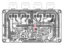
R14, the NFB upper leg resistor, can be soldered onto the Ro lead as it comes out of the output rail trace.
That ensures it reads the output voltage.
That would be ideal.
I've done a "sort of simple" universal speaker delay circuit here as I often mention the need... but never show a circuit.
http://www.diyaudio.com/forums/soli...al-speaker-delay-using-triac.html#post3269862
http://www.diyaudio.com/forums/soli...al-speaker-delay-using-triac.html#post3269862
Hi Guys, I went over Alex PCB design and schematic and R10 looks like inadvertently it was put on signal ground instead of -45v. Was this a mistake?
I made a bom and will upload if others are interested. If so, what value should I put for the feedback resistor as per post 385.
Alex, you willing to review? It would be hard for me to build without pcb as I have never built amp without pcb.
Best to all, John
I made a bom and will upload if others are interested. If so, what value should I put for the feedback resistor as per post 385.
Alex, you willing to review? It would be hard for me to build without pcb as I have never built amp without pcb.
Best to all, John
Hi Guys, I went over Alex PCB design and schematic and R10 looks like inadvertently it was put on signal ground instead of -45v. Was this a mistake?
It is an error... well spotted... and it does indeed connect to the negative rail.
If so, what value should I put for the feedback resistor as per post 385.
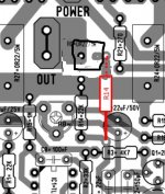
The feedback resistor is still 22K, its just the take off point that was open to interpretation/discussion.
Remember the exact point at which this resistor connects in regard to the physical layout, is the exact point which is used as a "reference" for the signal.
Ideally it should be on a spur like this.
Attachments
Two short video clips showing operation of the triac relay delay (post #389 in this thread) in operation,
http://www.diyaudio.com/forums/soli...-speaker-delay-using-triac-2.html#post3277146
http://www.diyaudio.com/forums/soli...-speaker-delay-using-triac-2.html#post3277146
Revisions for the amplifier "designed for music"?
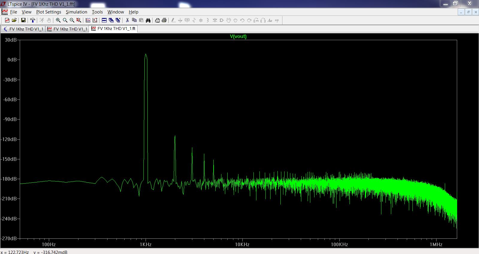
Hi Mooly. In a recent thread by Maouna you gave us a quick preview (i.e. the above distortion profile) of a revised form of your amplifier design. This is quite a development and no doubt you are pleased with it, as anyone taking up the design for a project will be if you care to detail what you have been up to.
I'm all err..."ears" to hear a little more about this quite interesting and commendable achievement, if I may say. That is an exemplary SPICE distortion "profile"!")
Hi Mooly. In a recent thread by Maouna you gave us a quick preview (i.e. the above distortion profile) of a revised form of your amplifier design. This is quite a development and no doubt you are pleased with it, as anyone taking up the design for a project will be if you care to detail what you have been up to.
I'm all err..."ears" to hear a little more about this quite interesting and commendable achievement, if I may say. That is an exemplary SPICE distortion "profile"!
Hi Ian,
it's all still very much "on the drawing board" so I don't want to give to much away at the moment but its evolutionary rather than revolutionary. Two pairs of dual die lateral FET's per channel with the VAS using two paralled small signal devices. An unusual feature I have been experimenting with in simulation is "distortion profiling". This allows via one variable resistor for the basic level of distortion of the amp to be increased (yes increased) while still maintaning that same FFT profile, while another variable resistor transfers the feedback from the normal takeoff point to earlier in the driver stages allowing the output stage to run more "open loop". The servo modifies a high precision reference voltage used for biasing rather than the servo providing the total bias voltage as in the original.
it's all still very much "on the drawing board" so I don't want to give to much away at the moment but its evolutionary rather than revolutionary. Two pairs of dual die lateral FET's per channel with the VAS using two paralled small signal devices. An unusual feature I have been experimenting with in simulation is "distortion profiling". This allows via one variable resistor for the basic level of distortion of the amp to be increased (yes increased) while still maintaning that same FFT profile, while another variable resistor transfers the feedback from the normal takeoff point to earlier in the driver stages allowing the output stage to run more "open loop". The servo modifies a high precision reference voltage used for biasing rather than the servo providing the total bias voltage as in the original.
Hi Ian,
it's all still very much "on the drawing board" so I don't want to give to much away at the moment but its evolutionary rather than revolutionary. Two pairs of dual die lateral FET's per channel with the VAS using two paralled small signal devices. An unusual feature I have been experimenting with in simulation is "distortion profiling". This allows via one variable resistor for the basic level of distortion of the amp to be increased (yes increased) while still maintaning that same FFT profile, while another variable resistor transfers the feedback from the normal takeoff point to earlier in the driver stages allowing the output stage to run more "open loop". The servo modifies a high precision reference voltage used for biasing rather than the servo providing the total bias voltage as in the original.
Mooly,
I understand you want to keep things secret but...
Your project sounds very interesting to me. I will be following this. Hopefully, you will provide us with an asc file to run in due course.
What sort of advantage do you see in the paralleled VAS devices? Do you find that the overall cob is lower this way? What sort of current are you running in this stage?
One last question, how do you set up Ltspice for you distortion profiles? We both ran a circuit for danny92 (I think). You ended up with an FFT looking totally different from what I got.
Paul
Well, this still sounds as mysterious as any other description I've yet heard for distortion profiling, FFT tweaking etc..... An unusual feature I have been experimenting with in simulation is "distortion profiling". This allows via one variable resistor for the basic level of distortion of the amp to be increased (yes increased) while still maintaning that same FFT profile, while another variable resistor transfers the feedback from the normal takeoff point to earlier in the driver stages allowing the output stage to run more "open loop". The servo modifies a high precision reference voltage used for biasing rather than the servo providing the total bias voltage as in the original....
 Good luck with this and keep us posted. After all, it is part of the main game here of improving our personal music listening enjoyment and your approaches always seem to me to be well focused and concieved.
 Mooly,
I understand you want to keep things secret but...
Your project sounds very interesting to me. I will be following this. Hopefully, you will provide us with an asc file to run in due course.
What sort of advantage do you see in the paralleled VAS devices? Do you find that the overall cob is lower this way? What sort of current are you running in this stage?
One last question, how do you set up Ltspice for you distortion profiles? We both ran a circuit for danny92 (I think). You ended up with an FFT looking totally different from what I got.
Paul
Hi Paul, the VAS stage runs at a fraction over 8ma in total. The parallel VAS is more of an experiment at the moment but seems to give good results.
I tend to run all the sims based on Bob C's excellent Spice tutorials in his book but run them over a longer period, at least 80ms (looking at the last 20ms) and try and take out the main R/C time constants (usually input and feedback electrolytic caps) that cause trouble with sims by replacing them with a DC offset voltage of identical value to that present in a sim of the full circuit with the caps.
Well, this still sounds as mysterious as any other description I've yet heard for distortion profiling, FFT tweaking etc.
Thanks Ian, and yes, its all about the music in the end
- Home
- Amplifiers
- Solid State
- My MOSFET amplifier designed for music