Hello Lumba Ogir,
Nobody else built one yet, only Michael the Spaceman")
Yes I aree that this is one area that could see improvement-- but as to audible differences- I don't know. It's quite feasible to use a simple shunt zener arrangement for this as the current draw is so low. The drivers for the outputs could not be included in this however.Lumba Ogir said:
I`m proposing separate, high voltage, well-filtered regulated power supply for the input.
Nobody else built one yet, only Michael the Spaceman
PCB revised with 2 pairs ....
Hello Mooly ,
PCB in this version http://i38.tinypic.com/10y0492.jpg it's ok or not , please tell me , I'm curious , best regards alex mm
Hello Mooly ,
PCB in this version http://i38.tinypic.com/10y0492.jpg it's ok or not , please tell me , I'm curious ,
best regards alex mm Mooly said:This is the Preamp in outline form.
----------
The series /shunt switching works brilliantly and give total isolation between inputs.
Even with something ridiculous like a 10volt peak/peak squarewave as an input,
there is no audible breakthrough even with volume on max.
Preamp circuit
http://www.diyaudio.com/forums/attachment.php?s=&postid=1452488&stamp=1205147327
Looks very good, Mooly.
JFET transistor signal switching is great in this way you do it.
The trick is to switch around the ground level.
This you achieve by using INVERTING input to op-amp.
Another detail. You use 22pF caps in OPA604 feedback.
Good!
It has been noticed some times, that OPA604 is not as unconditional stable as OPA134, OPA2134.
Those caps will ensure we do not get any unwanted oscillations.
Well done, Mooly.
Regars Lineup
Hi Lineup,
Thank you for your kind comments. As you say, putting the series FET at the inverting input ensures no voltage is developed across it. The 2SK152 seemed as good as anything and as a bonus they are ridiculously cheap, about £0.08 each from WWW.CPC.CO.UK in stock part number SC2SK152. The 0.1mfd on the gate gives a nice "soft switching" action together with 1 meg ohm gate resistors. It is important to not let the gate go more than about 0.3 volts positive as any higher and current will breakthrough the gate channel and cause a D.C. offset to appear on the output. It works O.K. with the gate at zero but that extra 0.3 volts really helps lower the final on resistance to about 30 ohms I seem to remember. Things like the 22pf caps I always like to decide on the final value when it's all completed, so as to take into account any board capacitance etc. You can't beat real world testing -- scope and sig gen-- and it's suprising how "critical" the correct value can be as you swing the amplitude from zero to maximum. The final value of R1 can also be tweaked for each input to make all inputs appear at the same volume.
Thanks again,
Karl
Attachments
Hello,
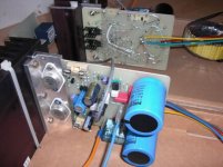
Today, I finished my "Mooly's amp" and everything seems OK. Bias stability is good, offset settles nicely to 0.1mV and even without the 0R22 output resistors, I can see nothing odd on my scope. No hum or buzz at idle with the ears close to my 92dB/W/m loudspeakers. Just a little hiss. I have to add a timer yet to feed the relays.
Differences with the original schematic :
- Single die BUZ9000/905 TO3 output mosfets
- Rails at +/-31V with 10000µF on each one
- An added RC cell to feed the voltage gain stages on each rail
- Driver and output stages are fused
- No PCB, just a piece of epoxy and point to point wiring
First listening, very good, nothing odd to my ears. Then I used a switch for direct comparisons. I did it with another mosfet amp, my only fet one until today, an SKA GB150D kit from Australia. Mooly's amp is good in bass performance, the SKA going only slightly deeper. Differences become to appear in the mids. While the SKA is keeping a same level of details over the entire spectrum, Mooly's one becomes slightly brighter at the expense of a lower resolution. The higher the frequency, the sweeter the sounding. On little bells recording, it becomes obvious that something is added, something that makes this amp sound like a tube one, close to my KT88 one. The 6L6 of a friend of mine distorts even more and he like it, but when it comes to solid state, he only likes low distorsion ones. Curious...
This was my first try with laterals, interesting and instructive. Many thanks Karl for sharing this design with us.
Francis
Attachments
Mooly said:Hi Lineup,
Thank you for your kind comments.
As you say, putting the series FET at the inverting input ensures no voltage is developed across it.
The 2SK152 seemed as good as anything and as a bonus they are ridiculously cheap,
about £0.08 each from WWW.CPC.CO.UK
in stock part number SC2SK152.
------------
Thanks again, Karl
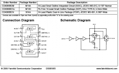
Your JFET swtiching of signal reminds me of this.
There is a CMOS chip with four, Quad Analog switches. I am sure you know.
CD4066 works at recommended max 15 Volt supply.
( Actually the Absolute MAX Supply is 18 Volt DC )
It has got ~ 80 Ohm ON resistance / 15 VDC
The ON resistance is matched to typical max delta 5 Ohm between switches in one IC.
The channel for signal is 2 mosfet, one NMOS and one PMOS in parallel.
As the ON resistance is rather low in compare with for example 10000 Ohm input impedance of a preamp
the eventual noise/distortion added is not much to write home to mama about.
80 Ohm : 10000 Ohm
Ratio 1:125 ( -42 dB )
If we say distortion is 0.1% ( -60dB ) we get -102 dBHigh degree linearity 0.1% distortion (typ)
when switching with a 10 kOhm resistor.
I hope I have not made any logical thinking error here ....
If so, you please correct me, Mooly
Datasheet:
http://www.fairchildsemi.com/ds/CD/CD4066BC.pdf
See attachment for basic operation information.
Attachments
Hello Francis,
That's fantastic - I am so pleased someone has built this successfully and it's interesting that you have compared it to a KT88 valve amp.
You can certainly go higher with the rails if you need to, I run mine at around 45 volts. Is the 10k feeding the OpAmp supply OK on 30 volts or did you need to drop it ?
Whether the following would make any subjective difference I don't know, but you can try increasing the 10 Mfd input cap to around 47 Mfd. The 150 pf cap at the input. I found no stability issues at all with removing this, and this is how I have mine, but if you try this perhaps run it up with a bulb or something first to give some protection in case it complains. The 1 Mohm feeding the servo. This forms a "pole" in the low frequency response of the amp. You could try increasing this, the only downside is that the output will take that bit longer to settle from switch on.
Other than the 150 Pf cap I haven't actually tried any of the above, but it could be worth a try to see if there is any subjective change.
Adding extra decoupling is good. It would be interesting to feed the input stages from a slightly higher supply than the outputs and drivers. As the current draw is so small a voltage doubler and zener network seems very do-able. The drivers and outputs must be fed off the same supply however with this output configuration.
Can I ask what speakers and source you are using
Edit. Did you fit an output inductor, the circuit ommited the 10 ohm across it, and did you keep the 0.22 ohm series output resistor. If so you may like to try tweaking this perhaps trying a 0.1 ohm or even ommiting. This is one part that does interact directly with the speaker impedance and does alter the subjective response.
Attachments
Hi Lineup
Used to play around with those CMOS chips a lot. In the configuration I use they would probably work well. Years ago I used some others, DG308,s ? I think they were, but thats quite a while ago now. If you look how I use the FET's, in a virtual earth amp there is never any significant signal developed over the series pass element. The on resistance of a FET & the 4066 varies in a non linear manner according to the voltage across it. This configuration helps avoid it. It works so well I have never felt the need to experiment with alternatives, in fact I have just stocked up with 30 or so 2SK152's ( Just in case )
Used to play around with those CMOS chips a lot. In the configuration I use they would probably work well. Years ago I used some others, DG308,s ? I think they were, but thats quite a while ago now. If you look how I use the FET's, in a virtual earth amp there is never any significant signal developed over the series pass element. The on resistance of a FET & the 4066 varies in a non linear manner according to the voltage across it. This configuration helps avoid it. It works so well I have never felt the need to experiment with alternatives, in fact I have just stocked up with 30 or so 2SK152's ( Just in case
)Hi KL
Nice to see your interest for this amp, you've still not succeed in the quest of the best one. If it happens, tell me.
This morning I made some mods and listened to "the guitar trio" of John Mc Laughlin. Very good sounding.
But don't expect an extreme resolution, the GB150D is way better in this regard. Comparing the bass range is somewhat unfair because it's psu is bigger and mine is fully dc coupled. Mooly's amp can't be. In term of speed, impact, they are very close.
I have many different amps at home, each one having something special and it generaly reflects the way the designer is feeling the music. In case of Mooly's amp, I would say it has been designed by a "romantic engineer".
Hi Karl
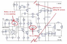
My power needs are so low that even a lower psu would do the job. For the safety of my speakers, I dropped the 10K to 6.2K so as not to end up with an underbiased opamp. And yes, I'm using the inductor with 10R across it but no serial output resistor. This morning I have doubled the time constant of the integrator, reduced the input low pass to 2.2K/100p, the input cap was already a 22µF. As I'm feeding the amp with a 10K ALPS pot, I've added an extra RC cell at the output of the opamp (33K/0.47µF) to filter out any noise produced by it. If there is a difference, it's tiny, I can't notice.
May I reduce slightly the overall gain without any harm ? My thought is to increase the feedback shunt resistor to ground, actually 470R and replace it with 620R for a 31dB gain. A I understand it, the feedback factor should remain constant and stability shouldn't suffer.
My source is a Marantz CD14 player and Cabasse Iroise speakers, a french brand.
Best regards,
Francis
Nice to see your interest for this amp, you've still not succeed in the quest of the best one. If it happens, tell me.
This morning I made some mods and listened to "the guitar trio" of John Mc Laughlin. Very good sounding.
But don't expect an extreme resolution, the GB150D is way better in this regard. Comparing the bass range is somewhat unfair because it's psu is bigger and mine is fully dc coupled. Mooly's amp can't be. In term of speed, impact, they are very close.
I have many different amps at home, each one having something special and it generaly reflects the way the designer is feeling the music. In case of Mooly's amp, I would say it has been designed by a "romantic engineer".
Hi Karl
My power needs are so low that even a lower psu would do the job. For the safety of my speakers, I dropped the 10K to 6.2K so as not to end up with an underbiased opamp. And yes, I'm using the inductor with 10R across it but no serial output resistor. This morning I have doubled the time constant of the integrator, reduced the input low pass to 2.2K/100p, the input cap was already a 22µF. As I'm feeding the amp with a 10K ALPS pot, I've added an extra RC cell at the output of the opamp (33K/0.47µF) to filter out any noise produced by it. If there is a difference, it's tiny, I can't notice.
May I reduce slightly the overall gain without any harm ? My thought is to increase the feedback shunt resistor to ground, actually 470R and replace it with 620R for a 31dB gain. A I understand it, the feedback factor should remain constant and stability shouldn't suffer.
My source is a Marantz CD14 player and Cabasse Iroise speakers, a french brand.
Best regards,
Francis
Hi Francis,
I had never heard of those speakers-had to Google it, they look very good and I am sure they sound it as well. Very nice
It's interesting to hear your comment on power requirements. I always smile when I see some of the other designs using 50 pairs of whatever !! In a domestic setting you don't need it.
There is no problem altering the feedback as you suggest, it won't upset anything at all. Adding extra decoupling from the OpAmp output may not be such a good idea as a second time constant is introduced. I remember playing around with this age's ago, not on this amp, and it caused problems. I think if I remember correctly it actually caused low frequency instability, particularly if the time constant were long enough.
I listen to mainly classical stuff, and find this amp excels on this, particularly strings - solo violin etc. There is non of the harshness or unpleasantness that makes you want to turn it down or turn it off. It always seems to deliver the goods somehow, something other amps I have owned have never consistently done. And I find the imaging first rate, instruments stand in their own space in the soundstage.
It's an interesting thought that I think Doug Self once mentioned. It was that if you didn't like the sound of a "perfect" amp then the answer was to have some front end unit that could "dial in" the required type of "distortion". Erm perhaps not
Hi Francis
Yes Greg's GB150D is very good Even so, it is interesting to look at other designs, such as Moolys. I am glad you built it, your comments are always appreciated.
Tell me, did you use the fuses in your 150D?
How much of a difference did DC'ing the NFB make. (I have probably asked you this before ... )
have a good day
Yes Greg's GB150D is very good
Even so, it is interesting to look at other designs, such as Moolys. I am glad you built it, your comments are always appreciated.Tell me, did you use the fuses in your 150D?
How much of a difference did DC'ing the NFB make. (I have probably asked you this before ... )
have a good day
Hi KL
If I use the fuses ?
Yes, for safety reasons I do. I don't know why you ask. If it has to do with the sound of fuses, I dont feel concerned.
I have even add one on each rail of Mooly's amp, but they only feed the driver and output stage to keep low offset in case of melting.
The GB150D allows for DC'ing and the caps have 0V across them, not the best for a long term reliable behaviour. As long as
you have control over your source, it's not an issue to DC couple.
Mooly's amp can't be DC coupled, the singleton input transistor needs a shifting. But the nice thing is that the input and feedback caps always have 5V DC across them.
Does DC'ing enhance something ? For me it has more to do with psychological reason...
Hi Karl
You're right with the added time constant at the output of the opamp. I had to reduce it for stability.
Actually I look at your preamp. I will try to source the fets. How do you feed the gates ?
Linear pot, DAC or something else ?
Francis
Hi Francis,
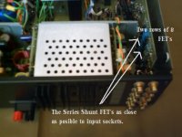
I keep looking at the picture you posted. What are the two objects on the back of the outputs -- they look like little heatsinks.
I know you say you ommited the 0.22 ohm series output resistor, but did you keep the 0.22 ohms in the Drains of the FET's.
You have probably seen the thread that's running on output inductors. How about trying without ? When I built this I didn't pay too much attention to this, in fact up to the finished version I didn't use one at all.
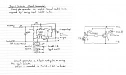
The preamp. When I built the amp it was done minus remote control, but this was something I always wanted to add later. The FET's are driven from a simple logic arrangement consisting of discrete transistors. Will try and draw out what I did. The gates must go no lower than around - 8 volts and no higher than around 0.3 volts. Use a 1 Mohm and a 0.1 mfd on the gate to give a nice soft switching action.
I designed the remote board as a "drop in addition" and it worked great. The front panel switch always has "control" and so if the CD input is selected and you then press tuner on the remote, the input and LED change to tuner, and the FET's switch.
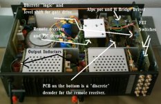
This of course means the control now doesn't point to the correct source but if the control is manually moved to a new position, the spare contacts on the switch generate a reset pulse (555 monostable) which resets the logic back to control by the front panel switch (same at power on as well) The remote receiver and PIC I had to buy as my PIC programming skills are zero. The PIC gives a "high" on one of 7 data lines corresponding to when a button is pressed on the remote. It will learn any common remote commands. These then feed into my "discrete decoder".
I even added a pot to vary the volts to the H bridge output stage. It's amazing how critical it is to get a good "speed" on the motorized volume control. Nothing worse than a pot that takes all day to get there or else whizzes round that fast you have no control
I keep looking at the picture you posted. What are the two objects on the back of the outputs -- they look like little heatsinks.
I know you say you ommited the 0.22 ohm series output resistor, but did you keep the 0.22 ohms in the Drains of the FET's.
You have probably seen the thread that's running on output inductors. How about trying without ? When I built this I didn't pay too much attention to this, in fact up to the finished version I didn't use one at all.
The preamp.
When I built the amp it was done minus remote control, but this was something I always wanted to add later. The FET's are driven from a simple logic arrangement consisting of discrete transistors. Will try and draw out what I did. The gates must go no lower than around - 8 volts and no higher than around 0.3 volts. Use a 1 Mohm and a 0.1 mfd on the gate to give a nice soft switching action. I designed the remote board as a "drop in addition" and it worked great. The front panel switch always has "control" and so if the CD input is selected and you then press tuner on the remote, the input and LED change to tuner, and the FET's switch.
This of course means the control now doesn't point to the correct source but if the control is manually moved to a new position, the spare contacts on the switch generate a reset pulse (555 monostable) which resets the logic back to control by the front panel switch (same at power on as well) The remote receiver and PIC I had to buy as my PIC programming skills are zero. The PIC gives a "high" on one of 7 data lines corresponding to when a button is pressed on the remote. It will learn any common remote commands. These then feed into my "discrete decoder".
I even added a pot to vary the volts to the H bridge output stage. It's amazing how critical it is to get a good "speed" on the motorized volume control. Nothing worse than a pot that takes all day to get there or else whizzes round that fast you have no control
Attachments
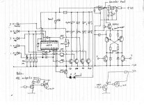
Found these, this is the logic for decoding the data lines from the PIC. I didn't use optos in the end as it shows, used the discrete transistor option. Notice the PSU. There is no ground reference as such. The -/+ 20 volts are from two regs I built into the main PSU from the start. This board "floats" between the rails ( not strictly true as the 20 volt supply defines where zero is ) I did it this way too avoid any ground currents being injected anywhere. Works brilliantly.
Attachments
Hi Karl
What you see underneath are little heatsinks on wich are bolted the 0.22R thick film drain resistors in TO220 package. There was no room on the upper side and I paid them such an outrageously high price that I don't want to fry them if something goes wrong. I suppose they are used for cross conduction reasons.
I will try without the inductor and monitor the output.
Thanks for all those informations about your pre. I was mainly interested by your antiphase circuit. I will try to feed the gates directly with a DAC driven by a PIC. It will give something very compact and I have some little experience with DACs and PICs.
Francis
Hi Francis
Yes, the fuses I was referring too are the one's that are part of the output, but included in the NFB circuit? I found, when I have replaced the fuses, that they do take at least 4 hours to run in and have at leaner sound to them ... have you noticed this.
thanks
Yes, the fuses I was referring too are the one's that are part of the output, but included in the NFB circuit? I found, when I have replaced the fuses, that they do take at least 4 hours to run in and have at leaner sound to them ... have you noticed this.
thanks
Mooly said:Hi Lineup
Used to play around with those CMOS chips a lot. In the configuration I use they would probably work well.
Years ago I used some others, DG308 ?
Yes, I recognize & remember DG308 hi-fi analog switches.
Quite expensive .. but very good.
There are more 'modern' such hi-fi quality analog switch chips around now. But generally, if they have very low distortion, like your JFET setup Mooly, you will have to pay for it.
Another option is of course low level REED RELAY.
These are my favourites
I have seen them used in Ultra Hi-Fi Pre Amplifier Projects!!!!
An externally hosted image should be here but it was not working when we last tested it.
Manufacturer: SRC Devices
Reed relays in a DIL- (dual-in-line) design. The relays require a small PCB surface, have a long life and are easy to operate.
They are epoxy cast in a DIL package in a 14 pin size and can be mounted automatically, wave soldered and washed.
PRME, PRMA
Relays for low and medium loads where a long life and high reliability are important.
The relays are built up around Clare's reed switch DYADTM which has ruthenium coated twin contacts
and a guaranteed load from 0 level, dry-circuit, to 10 VA.
Original package: tubes of 25 pcs.
This model is interesting. Single in line, SIL, pinning.
Which give a very compact and small space at PCB.
2 OUTER pins for signal & 2 INNER pins for on/off ( 5 Volt )
Pin spacing is 5.08 mm
I am not sure they are of same contact data quality as PRMA, PRME.
An externally hosted image should be here but it was not working when we last tested it.
Datasheet, digikey:
http://media.digikey.com/pdf/Data Sheets/SRC Devices PDFs/DSS4, MSS4, MVS4, SIL4.pdf
- Home
- Amplifiers
- Solid State
- My MOSFET amplifier designed for music