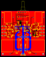
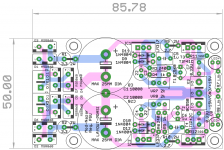
Thank Prasi, this is the first round.....not done yetHicoco, that's one hell of a schematic. Very professional, congrats!. Now show us the pcb when done😀
Regards
Prasi
Attachments
I wonder why this thread is still lurking about in solid state... should it be in the analog line level where it will have more viewership 🙄?
hicoco, that looks fantastic!
i've been wondering all along why this thread isn't in analog line level 😀
i've been wondering all along why this thread isn't in analog line level 😀
Prasi, thank again, this is very nice coming from you as you are a very fine PCB designer.
This preamp is an adjunction for my LM3886 amp, I have to ad a +-15V and +5V Stabilized Power Supply for the preamp and a Bluetooth audio receiver.
I have the power supply for the Amp (35V after the bridge).
I have 2 questions:
- May i use the same power supply with this schematic?
- if yes may i add it on the Preamp PCB just before the 220uf caps at the Preamp input
Attachments
Hello Hicoco,
You have asked a difficult question🙂. I am no expert, but I would suggest to keep it modular so that you could try different PSU if you feel the need, however everything on a single PCB makes it very comprehensive. Its your decision.
Beware of ground loops when designing / building , it can cause sleepless nights.
regards
Prasi
Have a look at the Nazar psu which i made pcb.
Its a terminal block. similar to this.
100PCS 2 Pin Screw Terminal Block Connector 5.08mm Pitch-in Terminals from Home Improvement on Aliexpress.com | Alibaba Group
100PCS 2 Pin Screw Terminal Block Connector 5.08mm Pitch-in Terminals from Home Improvement on Aliexpress.com | Alibaba Group
Thank you Prasi,
You did not use any heatsink for the regulators, look like for the preamp P88 it should be also not necessary.
You did not use any heatsink for the regulators, look like for the preamp P88 it should be also not necessary.
Hello Hicoco,
I soldered them from bottom side and mounted them on the bottom alu panel of case. But it was for 250mA per channel head amp.
In case of P88, heatsinking may not be required. Do monitor how hot they get. P88 shouldn't be consuming more than 10-20mA including any leds you may have in the supply.
regards
Prasi
Last edited:
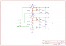
Yes, but coupling cap always has resistor to ground after it, it doesn't matter if it's input high pass filter or output high pass filter. They always go together. Cap + resistor = high pass filter that keeps DC out.
but then again some designs seem to use a coupling cap without a resistor. would that still be a dc blocking cap or does it serve a different purpose?
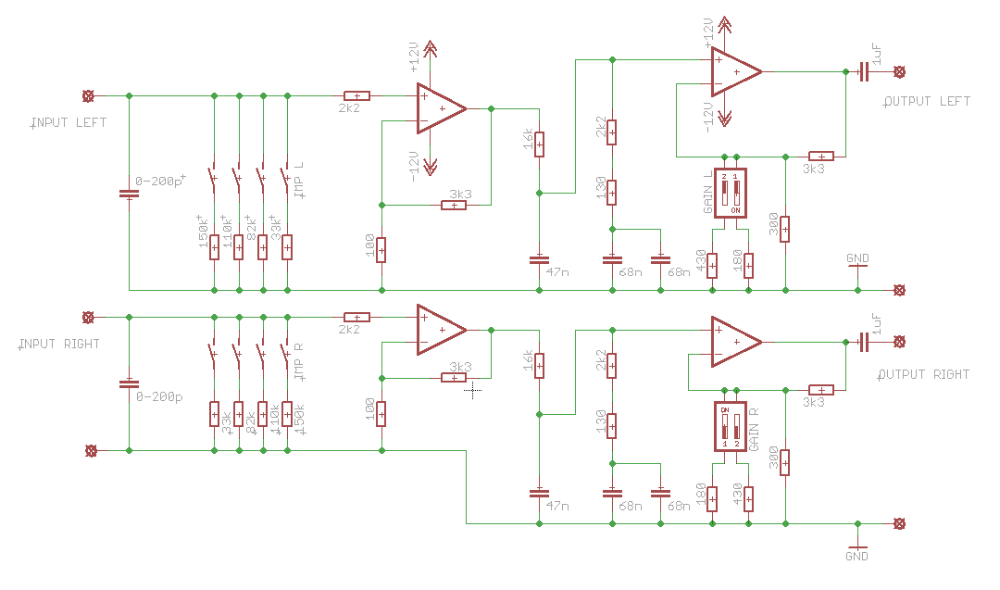
Without the resistor filter is not complete. In the case of the above schematic 1uF output cap will be in series with input cap of power amp (or some other preamp) and their combined value will be too low. Output filter should have resistor to ground or else output cap on the above schematic should be completely removed (if power amp has it already).
This look like RIAA circuit and there should be resistor to ground after 1uF.
This look like RIAA circuit and there should be resistor to ground after 1uF.
Last edited:
.png)
makes sense! thanks!
if a passive pre amp is used right after this schematic, say with a 20k volume pot, will the resistance of the pot add to the characteristic of the filter?
i'm thinking the 110k resistor would be in parallel with the 20k pot resulting in a 16,9k parallel resistance. together with the 1uF cap this should make for a roll off at roughly 9,4 Hz.
is my thinking right on this?
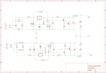
My ESP P88 build is under way. I've got the power supply board finished and the first stage of one channel. It sure is fun to see a voltage gain of 2 show up on the scope.
-Neil N0FN
-Neil N0FN
Attachments

- Home
- Source & Line
- Analog Line Level
- Rod Elliot Project 88 question