Ian if I understood Mr Self he thinks the ringing is the choke ? If I got that wrong please forgive as it was when the book came out when I was almost young. I was in Texas which was as hot as Austrailia. I was down by a small river with the not so safe wild life all on my own with the book. Huston was the big town about 5 miles away. It might have been August and > 40 C. I was doing my Mad Dogs and Englishman bit. I loved it. As always dressed head to toe in white and a hat plus bottle of water. I was given a lesson on snakes and crocs. Ayrton Senna was still alive as it was his pilots sister's house ( she worked with my ex ). I live near Silverstone, more exactly the airport they all use. Nick Fry ( Merc ) who I have never knowingly met lives in the next road across the football field I am told . OX20 1NS , see the stepping stones to the shed and field behind. Ross Braun also when he wasn't famous. What a nice man and Frank Derney also. He designed the Garrard Zero 100 when very young. Alas his version never was produced, the GT 55 was ( arm ).
Hi Nigel. Output coil ringing and its solution, was well known before D. Self's articles and books were published. Here in Oz, we had the work of Theile to guide us on the path, even before solid state arrived. Contemporary Japanese amplifiers and local DIY kit designs, even in the early 1970s, were fitted with low value resistors to damp the coil's "ringing" resonance. Many UK manufacturers however, seemed to resist change for decades, as the NAP 140 design shows.
For many years, local and overseas audio review publications featured extensive tests with 'scope images of output stage responses to a pulse driven into a standard capacitive load. Reviewers made quite a fuss and a lot of imaginative prognostication about it. As I read his articles, Self's thesis was just that this type of test was not as meaningful as many made out because it really only showed the interaction of the coil with a lumped reactance. In fact, I think most of his articles were a rebuke to established review journal opinion and many contemporary UK audio design practices.
Though we are drifting well off-topic again, I imagine this why so many UK industry people still have their noses out of joint regarding his proofs and views.
Thanks Ian. Like car suspension Q we can use taste. Why can't my car have a solonoid valve as it's resistor ? That is the oil hole in the damper. Soft for motorways and medium hard for the roads where I live. It would need no more input than a turn indicator to choose. Theres a thought. Three settings. It would add $50 to a car, or $100 if all four dampers. Doubtless Koni have them ?
I wouldn't be surprised if 100 R would be the better damper for a Naim. That is have your cake and eat it solution. In very old cars the grease in the spring leaf joins did some of the job. That might be true of modern versions of the same ? I dare say in the Outback the leaf spring still has it's pundits ? On second thoughts no as sand is not great for them. I think I am right in saying many SUV have them still ? I never did understand having a SUV when a Mercades Sprinter is so much better. Drive of your life if you haven't. Not least when lightly loaded ( 300 Kg ). Their cars I can take or leave. Long version needs a different driving style.
I don't think UK resists change. More like a religion where we love our first wife and try to keep her. I didn't manage that.
Well, I wasn't directing my comment about past manufacturers to the general UK populace. As many manufacturers are small businesses, they would have had to adopt a range of survival strategies in their shrinking stereo market. Some of these, such as maintaining old designs in production, have seemed counter-productive for the the ever changing tastes of the broader market. I feel this further hampers their efforts....I don't think UK resists change. More like a religion where we love our first wife and try to keep her....
Re output coil: I think 100R will have zero damping effect and likely introduce some resonant sound effects into the audio band that you may have hoped to avoid. R needs to be low, as in the order of the load impedance or less to damp anything, as suggested earlier.
Last edited:
I did a bit of maths . I have never questioned it before. 1 uH does virtually nothing at 100 kHz. At 1 MHz it would be 6R3 . Anyone like to say how it is helping ? As these inductors were common with low FT transistors it looks complex. It looks like 10 uH would be more the thing. Looking at Maxim they state 47 uH for a class D chip. They set roll off a bit lower than Hypex. Maxim see speakers as 10 uH ( no idea myself ). The Zobel is easier to understand. Could it be the inductor is a resistor and that's all it ever was ? Some speaker cables are said to be trouble. However the speakers seem worse. Don't mind being stupid on this one. Would like to know exactly why. I suppose 30 Mhz devices like 30 MHz. It still doesn't say what 2N3055 needed 30 MHz protection for. Would not 10 uH be better ? If these inductors do help sound as people say surely it's reduced damping factor that is prefered which will give slightly fuller bass. I can not think -0.1 dB in the bat hearing range is doing it. Conversely when the choke rings this makes the amplifier seem to slew faster ( or what we imagine that sounds like )? If so damping it will stop it seeming better. Although I can't prove it I think class D sounds a bit bright at the top end due to how it works. The 50 kHz or whatever roll off sounds like it would be higher compared to amps I know. This really begs the question how someone at 60 can detect this? I still can and proved it very recently when I fitted a 2 uS fiter that certainly worked. OK I know it is complex. All the same the next stage was able to accept the signal. I can not hear above 15 kHz as a tone. To my ears the Hypex with SMPS sounds brighter still although not unpleasent. The Hypex seems about 20 db down at 400 kHz ( modulator ). The SMPS measures as having more RF output. Could it be that the undamped choke could be a plus factor?
I think you are looking at the output coil and damping resistor as a simple, isolated parallel LR filter which it isn't, when lumped with the cable inductance and speaker crossover network.
Historically, the optimum value for L was proposed as 6.8 uH, because it was said to render solid state amplifiers "unconditionally stable" with loudspeakers and leads of the day but that concept and the outcome, has been demonstrated to intrude on flatness in the audio band and influence sound quality. 3uH has been the median in most power amplifiers for the last 20 years or more. Here on DIY audio, some think the inductance value is entirely arbitrary and you can tailor this safety device to your aural "taste" - often the less inductance or none is said to be best. I guess if you never stretch a DIY amplifier to its nominal limits, you can get away this senseless approach. In my situation, I am obliged to have defined and assured specifications when I build and sell something. It must perform to specification limits in all reasonable circumstances or I am liable for consequences like failure, oscillation, speaker and fire damage.
Because designers cannot control what you connect the amplifier to, they should responsibly ensure that the amplifier remains stable when used with all likely speaker arrangements. Naim instead, insisted on a certain cable type and then recommended only certain loudspeakers of the day. I can vouch for the damage that occurs when you did otherwise with the original amplifier, particularly in hot conditions.
Incidentally, Avondale's expensive NCC200 Naim clone module is claimed by quite a few users to be a notch above Naim sound quality yet it is little different except that it uses sluggish On-Semi output transistors and a small coil, chosen according to cable/speakers - a real fiddler's paradise for some but a worry for others.
Also, there are numbers of texts explaining the function and design of the output coil, including Self's work and lots of websites with rather hand-waving explanations even worse than mine. I don't profess to be an e.engineer so I don't go there. For interest, PMA is a consulting audio expert and contributed some interesting, if controversial work here: http://www.diyaudio.com/forums/soli...mplifier-output-coil-frequency-response-2.htm. Check his model's test component values and visit his website too - some nice, quality projects there and support threads here too. Good reading")
Historically, the optimum value for L was proposed as 6.8 uH, because it was said to render solid state amplifiers "unconditionally stable" with loudspeakers and leads of the day but that concept and the outcome, has been demonstrated to intrude on flatness in the audio band and influence sound quality. 3uH has been the median in most power amplifiers for the last 20 years or more. Here on DIY audio, some think the inductance value is entirely arbitrary and you can tailor this safety device to your aural "taste" - often the less inductance or none is said to be best. I guess if you never stretch a DIY amplifier to its nominal limits, you can get away this senseless approach. In my situation, I am obliged to have defined and assured specifications when I build and sell something. It must perform to specification limits in all reasonable circumstances or I am liable for consequences like failure, oscillation, speaker and fire damage.
Because designers cannot control what you connect the amplifier to, they should responsibly ensure that the amplifier remains stable when used with all likely speaker arrangements. Naim instead, insisted on a certain cable type and then recommended only certain loudspeakers of the day. I can vouch for the damage that occurs when you did otherwise with the original amplifier, particularly in hot conditions.
Incidentally, Avondale's expensive NCC200 Naim clone module is claimed by quite a few users to be a notch above Naim sound quality yet it is little different except that it uses sluggish On-Semi output transistors and a small coil, chosen according to cable/speakers - a real fiddler's paradise for some but a worry for others.
Also, there are numbers of texts explaining the function and design of the output coil, including Self's work and lots of websites with rather hand-waving explanations even worse than mine. I don't profess to be an e.engineer so I don't go there. For interest, PMA is a consulting audio expert and contributed some interesting, if controversial work here: http://www.diyaudio.com/forums/soli...mplifier-output-coil-frequency-response-2.htm. Check his model's test component values and visit his website too - some nice, quality projects there and support threads here too. Good reading
Oops, link is bad, try: http://www.diyaudio.com/forums/soli...amplifier-output-coil-frequency-response.html ...err thanks AndrewT, you found it too.
I'm glad I asked. Very well argued. 6.8 uH is good to know if only as a landmark. I am getting an uneasy feeling we shouldn't damp the coil. Was it only to get it past Hi Fi News " why bother to listen " Gordon J King test bench circa 1985. When I have damped coils the sound seems thin. Doubtless the coil is doing something wrong. It is the sort of wrong I like. 1R I like very much with no coil . I will be going to a friends house soon. He made the mistake of letting the nurse wash out his ears every few weeks. I am convinced it damaged them. He now can not listen to real music as it is too load. He complains his system lacks bass. I will ruin his damping factor to see if we can get what he needs. Failing that the only Naim NAP 250 with Quad 33 control unit. I have made minor upgrades to the 33 and have to say I love the design. It's a Land Rover when a Land Rover is what you need. It needs very careful gain setting to work. If it sounds bloated or thin then you have the wrong gain. Eg Denon DL 110 , Set 220R gain resistor to 130 R. If not thin.
If Malcolm's damping factor test comes to anything I will let you know. 1R 3R3 4R7 8R 11 watt. Being wire wound they will have a little inductance. His speaker 6R. In the 1950's when speakers were made to work with typical amps of the day a damping factor of 3 was said to be enough. Non inductive T0220 type power resistors exist. They are not too bad on price. That is if wanting to know if pure resistance matters.
I like the sound of thin speaker wire. 0.6 mm dia solid core ( 4 M ) . Perhaps I like lower damping factor?
You have to kill the HF ringing which is the typical instability all those old 'scope shots demonstrate. That is the whole point of fitting the damping resistor. Amplifiers up to even 150W only need 1W carbon film resistors - don't use any wirewound types - period.
The no-coil alternative is easily achieved by sacrificing slew rate. Rod Elliott's P3a DIY design, a very popular design here for great sound quality and newbie friendliness, has no coil and is used as a reference model here:
Elliott Sound Products - Audio Power Amplifier Design Guidelines
60-80W Power Amplifier
It is good stuff. I think what Rod writes has more value than many "expert" opinions. His MOS FET amps found the same as me, they work. As he says up to 10 kHz zero bias is almost OK, try that with bipolar. That must say something good about MOS FET's. You wouldn't think so reading the experts. Slew rates also seems not well explained. Do as you are told seems how it is explained. For example 6 V/uS seems on paper to be the ideal slew rate for a 100 W / 8 R amplifier. The real slew rate is 2 V/ uS , 6 allows for modern music. After that no tweeter will live. When I say 150 V/uS not required I am told I am an idiot etc. Mostly because highly respected people have done it. If this standard was applied to drinking water we would have none. I do know why it matters and it isn't difficult to work out. It is an elephant in the room. What it isn't, is people hearing the need for the speed. In the Beverly Hill Billy's grandma always knew there was someone at the door when she heard " that music " again. No one had told her what the doorbell was. We have a lot of that in audio.
Thanks Ian. You obviously do know that doorbell. That point about CC resitors is excellent. They have made a comeback as in pulse applications they hold up better. Now a very odd idea. I use them for pick up loading. The coil resistance swamps the 47 K so noise is OK ( I have graphs if people doubt it , foil types included ). Strangely the 1950 sound is had and is in some ways preferable ( darker and less sibilant ). Tyco foil the best, they cost a bomb. I wouldn't know this except a respected PU maker sent the foil types for me to try. I wish he hadn't. The sound difference was that with metal film the stylus always sounds dirty. All other resistors in the circuit were MRS25 or rod type 1205 SMD. Of the 3 CC measured best when loaded !!!
One thing I slightly don't agree with Rod over is that single input transistor amps are more stable. As far as I can tell this was due to transistors of the day having higher capacitance. I built examples and found perhaps reduced capacitance, seldom none. I have been playing with a 140 V op amp idea. It almost works as single input device. Maybe I will try harder and test the theory. MPSA 42 and 92 that hover in the 3 pF area. This op amp is to drive power valves. If anyone asks, it is to have a wire with gain and hear just the power valves before looking at a driver. The driver of choice might be an ECC 82 cascode with UL feedback at 8 mA. On paper it could beat the op amp as it's distortion in antiphase might be similar to a UL EL 84. I am working the EL 84 in LTP. That will need about 30 V rms to drive. A lightly loaded 100 watt amp would be OK. EL 84 quads might give 20 watt 0.7 % THD in UL. If the driver is about 0.7% THD which seems possible when ECC82 the amp might have 0.1% total. No loop feedback. I can not find a reliable Rp for 84 UL . I will guess it to be 1 to 1 with the load. My speakers are mostly resistive 4 R so it could work. In NAP140 terms I have a 8R resistor in series with the load.
That's why this hobby is so interesting
In my version of the amp with MJL3281 output transistors nothing sounds better than the 0.15 ohm metal element Ohmite resistor that I ended with. I strated at first with inductor/resistor combinations... My findings are somewhere in this, now quite big, thread.
Hello Ruwe
How many watts has your Ohmite resistor ,and is the resistor paralel with a Inductor or alone to the Output?
Ibuild already a nap clone and it works,and sounds good.
Before, i build tubeamps class d amps and so on.
But everithing i build ,i build with a lot of halfnowing and mistakes,
but in the end its running . I read the full thread and
my technical englisch is very bad and so i dont understand a lot.
And now comes my wish , can you perhaps put youre shematic of the nap with all the tunings and parts you change in this thread .because you have alot of experience with this amp.
I think it is intresting for more people and me.
please put youre 5 cent to it
Regards Andreas Germany excuse bad englisch
please put youre 5 cent to it
Hi Andreas,
Sorry for the late reply - really busy week.
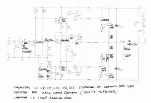
I attach my latest revision of the amp. I think it's self-explanatory and not original in any way.
After many months of tweaking I finally came back very close to the original version. Most modifications either don't sound that good to my ears or don't make any noticeable change, so I removed them. Some of them have strong technical reason, though. It's up to you to try, but this is my take on the amp. I have decent test equipment at home and excellent at work, but after all for music I use my ears.
Based on PRAT, most people presume clinical sounding amplifier. I think this Naim circuit is rather warm and on the dark side of the audio spectrum. It's not super detailed or deep, but somehow right - present, wide and satisfying. Great for DIY, easy to build and cheap.
Most problems with it come from poor wiring techniques. If I had a nice machine shop at home I would have made any amplifier, power supply and speaker terminals attached to common copper bussbars and not wired.
On the latest discussion about the output coils: I also used to advocate for coil/resistor at the amp output, but not anymore. If you test in purely resistive load, coil is fine. Put few nF capacitance in parallel to the load resistor and tell me what you see on the scope when you sweep the generator through the high frequencies.
I think that many cables and speakers may have and will have capacitance. Ask any tech - they will tell you that oscillation is tamed with resistors not with coils.
In addition, 0.15 ohms of quality resistor may be similar to the resistance of long runs of cables or poor terminal connections, loose bananas, dirty contacts etc. I don't think it's such a big deal about the damping factor as well, unless the speakers have really, really bad crossover design and resonance behaviour or have super low nominal impedance.
As a disclamer: I'd like you to know that I don't listen to this amplifier anymore. Lately, I played a lot with «current-feedback» designs similar to Hiraga and Pass F5 schematic and found them to be interesting and challenging.
In the end, I built a tube amplifier and since then I lost any interest in transistors for home audio. The best indication that you have something that you really like is when you don't want to open the cover and «improve» it, when you don't salivate after new models in hi-fi magazines and trade shows or scrutinize schematics on diyaudio with pile of electronics books on the table before you
There is something in tubes that makes you to like them. A lot! ... And for sure it's not their perfection.Attachments
Last edited:
Hi Nigel. If you are asking for recommendations for an original Quad 303 system, you'd be better off looking at Quad threads or on forums oriented to commercial UK products generally. Not many DIY folk would have or be able to buy decent, 40+ year old ESL 57 speakers to have a qualified opinion but sometimes, the odd pearl of wisdom is seen here, for example: Quad 57 recommended Speaker Cables - pink fish media.
This one is for amusement: speaker cable for QUAD 63?
The Ultimate Quad site is Dada of course, but you may have to wade through many pages and sort from promotional tripe to find useful material: Quad Spot
This one is for amusement: speaker cable for QUAD 63?
The Ultimate Quad site is Dada of course, but you may have to wade through many pages and sort from promotional tripe to find useful material: Quad Spot
Last edited:
Nigel,
The cheapest Nordost stuff is also good. And they have data. I don't buy cables without specs. When I bought mine I measured it and found the capacitance and inductance to be as published.
CAT5 is very capacitive and performance depends on how you select the twisted pairs - split or together. Results: unpredictable. This is the only cable that I've seen the 140 clone to oscillate with. I don't understand why diy-ers like it. May be, because it's cheap and easy to find.
NAC A5 is also good cable, but horrible to work with. Sooo stiff. I gave up on it and sold it.
- Home
- Amplifiers
- Solid State
- NAP-140 Clone Amp Kit on eBay