It was always a mystery how well the NAP 140 etc worked. I think the heat fuse saved the day.
T23A070ASR2-15 - HONEST-WELL - THERMAL SWITCH, NC, 70°C | CPC UK
T23A070ASR2-15 - HONEST-WELL - THERMAL SWITCH, NC, 70°C | CPC UK
Finally, i had lots of time to play with that kit, mainly because i got new speakers(Vintage OR-H70) Produced in Finland.
Despite that they are closed type box, they are playing all the way down to ~35hz.
Previously i used small = ~4.5inch 20W full range, also dull sensitivity about ~84dB.
Sound OK, they do good Bass also
But now, these Suomi Speakers.....Amplifier is automatically Turned OFF@ Loud Volumes(30-40W), because the sound gets so awful AT 3kHz+ range.
For instance, Volume below 40% is OK, almost soft to ear and everything is good, almost.
Rising volume from 40% and up, i loose drums(compression), everything goes to harshh and my ears starts to bleed, seriously whats the problem ? Only one good thing is that BASS is playing really deep, good, controlled, everything Else is BS...
Speakers are ok, both of them good DC resistance..
I have tried lots of modifications on the schematic except VAS and LPT stages.
1. Removed 220ohm Front-End PSU filtering resistor(Separate Regulted SUP).
2. Replaced ceramics with MKP WIMA except compensation(56pF<-- replaced with 68pF NPO for less Oscillations).
3. Output inductor is now paralleled with 6.8OHM Carbon resistor.
4. All AC coupling and feedback capacitors are now Tantalums/WET, BC Components 128 <---exact same values as in NCC200 newest schematic.
Turn on(Front-End - Regulated PSU(Avondale VBE+ Output - Capacitor Bank Filter PSU): Sound is different.... The highs are altered a little, more background and more middle frequency stuff, bass good. Sometimes everything seems so strange and new
@ Loud Volume, still whines like a bitch....
Then:
Re-done some front-end decoupling grounds.. more separate.
Replaced TIP Drivers with BD139-16ST and BD140-16ST, made bypass on a feedback capacitor(68uF Solid Tantalum) with a 100nF MKF WIMA.
Turn on, Oh my Lord... it just sounded so AWful even @ 40% volume and then the Headache....madness witch was followed by Turning off the AMP again
Strangely, the HeatSink was always warm, even then, when music stopped playing for about 20min <--- hardcore oscillations. It got cooled down but, took too much time
REMOVED BD139/BD140 before destroying something! Installed TIP´s back.
Set the bias twice, first @ 5mA per device as China has recommended in pinkfish media forum. So, H-140 gets 14mA per channel of bias.
Turn on: I just can´t believe my self in what business i have gone into... It sounds still so bad.... Turn off indeed
Second time: Set the bias to 38mA as everyone are suggesting....(pinkfish media and so on).
Turn on: More Bias helps, I have Noticed that i could hear more Background with Higher Bias and Crank the Volume a little bit more upwards before the AMP forced me to SHUT IT OFF AGAIN.
SPECS: So, Everything is overpowered in therms of 500VA Xformer + 120VA Xformer, PSU caps, Regulated PSU, Capacitors(Even exotic one´s) but still bad sound ?.
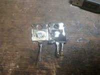
Next step: Removing output transistors that i got with the Ebay h-140 kits(2SC5200).
I had some more 2SC5200 laying around from Polish supplier.
Comparing China to Polish, both look same, crack them open and see:
China has about ~3mm Die Size, Polish had ~3.7mm Die Size, in terms of copper and everything else, they are same.
Installed now Polish 2SC5200 back to the H-140 kits.
Turn on: Turn Off, the End...
Conclusions: Output Transistors 2SC5200 are bad for these kits ?
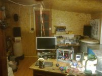
Maybe the Room and the stuff within the room are resonating @ 3Khz + ?
Could it be separate powersupply topology ? If i remember, i got less details and background with only 1 filterbank supply for both channels but a warmer sound and stable @ high volumes( stable in sound wise and compression, amp itsself was oscillationg for sure as do all H-140 on E-bay!)
Also, there is no point to go back to just 1 unregulated PSU, loosing all the background is not an option anymore...
Despite that they are closed type box, they are playing all the way down to ~35hz.
Previously i used small = ~4.5inch 20W full range, also dull sensitivity about ~84dB.
Sound OK, they do good Bass also
But now, these Suomi Speakers.....Amplifier is automatically Turned OFF@ Loud Volumes(30-40W), because the sound gets so awful AT 3kHz+ range.
For instance, Volume below 40% is OK, almost soft to ear and everything is good, almost.
Rising volume from 40% and up, i loose drums(compression), everything goes to harshh and my ears starts to bleed, seriously whats the problem ? Only one good thing is that BASS is playing really deep, good, controlled, everything Else is BS...
Speakers are ok, both of them good DC resistance..
I have tried lots of modifications on the schematic except VAS and LPT stages.
1. Removed 220ohm Front-End PSU filtering resistor(Separate Regulted SUP).
2. Replaced ceramics with MKP WIMA except compensation(56pF<-- replaced with 68pF NPO for less Oscillations).
3. Output inductor is now paralleled with 6.8OHM Carbon resistor.
4. All AC coupling and feedback capacitors are now Tantalums/WET, BC Components 128 <---exact same values as in NCC200 newest schematic.
Turn on(Front-End - Regulated PSU(Avondale VBE+ Output - Capacitor Bank Filter PSU): Sound is different.... The highs are altered a little, more background and more middle frequency stuff, bass good. Sometimes everything seems so strange and new
@ Loud Volume, still whines like a bitch....
Then:
Re-done some front-end decoupling grounds.. more separate.
Replaced TIP Drivers with BD139-16ST and BD140-16ST, made bypass on a feedback capacitor(68uF Solid Tantalum) with a 100nF MKF WIMA.
Turn on, Oh my Lord... it just sounded so AWful
even @ 40% volume and then the Headache....madness witch was followed by Turning off the AMP again Strangely, the HeatSink was always warm, even then, when music stopped playing for about 20min <--- hardcore oscillations. It got cooled down but, took too much time
REMOVED BD139/BD140 before destroying something! Installed TIP´s back.
Set the bias twice, first @ 5mA per device as China has recommended in pinkfish media forum. So, H-140 gets 14mA per channel of bias.
Turn on: I just can´t believe my self in what business i have gone into... It sounds still so bad.... Turn off indeed
Second time: Set the bias to 38mA as everyone are suggesting....(pinkfish media and so on).
Turn on: More Bias helps, I have Noticed that i could hear more Background with Higher Bias and Crank the Volume a little bit more upwards before the AMP forced me to SHUT IT OFF AGAIN.
SPECS: So, Everything is overpowered in therms of 500VA Xformer + 120VA Xformer, PSU caps, Regulated PSU, Capacitors(Even exotic one´s) but still bad sound ?.
Next step: Removing output transistors that i got with the Ebay h-140 kits(2SC5200).
I had some more 2SC5200 laying around from Polish supplier.
Comparing China to Polish, both look same, crack them open and see:
China has about ~3mm Die Size, Polish had ~3.7mm Die Size, in terms of copper and everything else, they are same.
Installed now Polish 2SC5200 back to the H-140 kits.
Turn on: Turn Off, the End...
Conclusions: Output Transistors 2SC5200 are bad for these kits ?
Maybe the Room and the stuff within the room are resonating @ 3Khz + ?
Could it be separate powersupply topology ? If i remember, i got less details and background with only 1 filterbank supply for both channels but a warmer sound and stable @ high volumes( stable in sound wise and compression, amp itsself was oscillationg for sure as do all H-140 on E-bay!)
Also, there is no point to go back to just 1 unregulated PSU, loosing all the background is not an option anymore...
Attachments
It's not clear what combination of measures you tried are still in place and what your current design/schematic is, so I don't think we can really make helpful comment on what happened. I don't think that using high Ft transistors is in itself a problem but the frequency compensation and other stabilising options have to be adapted to suit the devices used, like 2SC5200/A1943 in Ebay clones or the even faster Sanken types fitted by Naim in all larger original models. The Toshiba transistors are now obsolete and genuine replacements are now TTC5200/A1943 or the new TOP3 2SC5200N/A1943N3. All these new Toshiba versions have smaller dies. Despite the low cost of the genuine parts, what you get now from China sellers will have an even higher likelihood of being a fake, good or bad, unless you buy direct from bona fide distributors.......Maybe the Room and the stuff within the room are resonating @ 3Khz + ?
Could it be separate powersupply topology ? If i remember, i got less details and background with only 1 filterbank supply for both channels but a warmer sound and stable @ high volumes( stable in sound wise and compression, amp itsself was oscillationg for sure as do all H-140 on E-bay!)
Also, there is no point to go back to just 1 unregulated PSU, loosing all the background is not an option anymore...
[/COLOR][/COLOR]
It seems that overall, you've changed the stability margins of the design without checking, or rather measuring, what occurred at each stage. Now you could have quite a number or combination of errors. It's not simple to buy and set up test instruments, but if you want to tackle amplifier design with classical bench methods, you are going to have to measure and plot the results to determine the problems as they occur.
Have you considered downloading free Spice programs like TiTina or LTspice? Checking your circuit and changes this way first, can avoid a lot of time and money on parts, tests and construction. Changes based on the usual "audiophile" mods mantra may seem like a good idea when you read the glowing testimonials on the 'net but may still be flawed from a technical point of view or simply not compatible with your particular design as it stands.

Hi Nigel
Rensli has previously modified the front end with separate supplies and more, IIRC. I'm uncertain what the present design is, apart from generally following the latest Avondale clone schematic so I couldn't say how to go about rescuing the present situation as the semis don't appear to match either design. The compensation cap is already increased which is reasonable if 2SD667/B647 are used for the VAS transistor and CCS. They are somewhat lower capacitance than ZTX653/753 and 39pF could be raised to 47 pF in any case.
Even so, I don't like the sound much using the Chinese VAS pair and like Ruwe, I've found the most satisfactory results in just tweaking the clones rather than changing them radically. There are other kits for not much money that can be more easily modified to the usual "audiophile" recipe or just used as pincushions for whatever gold plated parts people want to cram in.
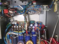
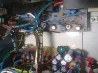
My concern now is that the design is likely unsuited to the semis in use and has radical changes, including super-low impedance power supplies using many small low ESR caps, which is frowned upon these days. I am looking at those images of neatly bundled supply and output leads leads too and thinking how much coupling between the bulky wiring has affected the stability, noise and distortion. It might be OK to wire mains power in an appliance that way but not an amplifier.
It would be a pity to dismantle the wiring but I suspect there is more a problem there than than any benefit. Consider the current required by the front end - about 10 mA per channel and Rensli, you are using ~1 mm CSA flex? Small hookup wire, twisted together as far as possible or even shielded as in balanced mic. cable, would be a more sensible way to connect the extra supplies. For that matter, all supply lead pairs, mains pairs, output pairs should be tightly twisted and located well away from signal leads, signal level circuits and sources of EMR rather than random bundled in looms.
Placing the output coils directly over the input stage of an amplifier (was that just for the pic?) is another way to couple the input to output and introduce positive feedback and oscillation. Usually this is capacitive coupling, producing a pulsed sound called motorboating but perhaps here it is related to the 3 kHz noise? I'd test without the coils in place or relocate them at the output terminals to see what, if any effect they may have.
Rensli has previously modified the front end with separate supplies and more, IIRC. I'm uncertain what the present design is, apart from generally following the latest Avondale clone schematic so I couldn't say how to go about rescuing the present situation as the semis don't appear to match either design. The compensation cap is already increased which is reasonable if 2SD667/B647 are used for the VAS transistor and CCS. They are somewhat lower capacitance than ZTX653/753 and 39pF could be raised to 47 pF in any case.
Even so, I don't like the sound much using the Chinese VAS pair and like Ruwe, I've found the most satisfactory results in just tweaking the clones rather than changing them radically. There are other kits for not much money that can be more easily modified to the usual "audiophile" recipe or just used as pincushions for whatever gold plated parts people want to cram in.
My concern now is that the design is likely unsuited to the semis in use and has radical changes, including super-low impedance power supplies using many small low ESR caps, which is frowned upon these days. I am looking at those images of neatly bundled supply and output leads leads too and thinking how much coupling between the bulky wiring has affected the stability, noise and distortion. It might be OK to wire mains power in an appliance that way but not an amplifier.
It would be a pity to dismantle the wiring but I suspect there is more a problem there than than any benefit. Consider the current required by the front end - about 10 mA per channel and Rensli, you are using ~1 mm CSA flex? Small hookup wire, twisted together as far as possible or even shielded as in balanced mic. cable, would be a more sensible way to connect the extra supplies. For that matter, all supply lead pairs, mains pairs, output pairs should be tightly twisted and located well away from signal leads, signal level circuits and sources of EMR rather than random bundled in looms.
Placing the output coils directly over the input stage of an amplifier (was that just for the pic?) is another way to couple the input to output and introduce positive feedback and oscillation. Usually this is capacitive coupling, producing a pulsed sound called motorboating but perhaps here it is related to the 3 kHz noise? I'd test without the coils in place or relocate them at the output terminals to see what, if any effect they may have.
Solution might have been found.
In my opinion its a source where the AMP is connected to. It is a Computer DELL Optilex 780 rear 3.5mm analog OUT.
Before receiving OR-H70 Suomi Speakers, i changed my primary computer from laptop to that Desktop DELL and at the same night i got my hands on Suomi speakers....
Now, i get the same sound comprossion and a headache with Audio-Tehnica ATH-A900 Closed Metal Cans headphones connected DIRECTLY to that audio port
The distortion of the sound reminds me a little NE5534 driving a 40ohm headphones directly without any buffer/current output stage.
After setting UP the Laptop, connecting AMP to it, i get what i was looking for in terms of sound
Ian Finch, coils are far 5CM away from PCB-s
CSA FLEX, you mean standard AC Wire ? If so, then yes, they are ~17-18AWG.
Front End is on spot or exceeds 10mA range
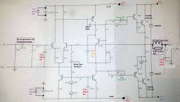
I attached a schematic of the Exact PCB-s i am listening to right now.
In my opinion its a source where the AMP is connected to. It is a Computer DELL Optilex 780 rear 3.5mm analog OUT.
Before receiving OR-H70 Suomi Speakers, i changed my primary computer from laptop to that Desktop DELL and at the same night i got my hands on Suomi speakers....
Now, i get the same sound comprossion and a headache with Audio-Tehnica ATH-A900 Closed Metal Cans headphones connected DIRECTLY to that audio port
The distortion of the sound reminds me a little NE5534 driving a 40ohm headphones directly without any buffer/current output stage
.After setting UP the Laptop, connecting AMP to it, i get what i was looking for in terms of sound
Ian Finch, coils are far 5CM away from PCB-s
CSA FLEX, you mean standard AC Wire ? If so, then yes, they are ~17-18AWG.
Front End is on spot or exceeds 10mA range
I attached a schematic of the Exact PCB-s i am listening to right now.
Attachments
Last edited:
Hi rensli,
Thanks for the updated schematic. It's good to hear that you found the problem lies with the PC soundcard but I guess its warranty has expired. I don't think I've had that degree of a problem, even using the wrong socket with PCs and Laptops but maybe Dell has a unique design. I now use a USB card or DAC to reduce hum and compatibility problems for tests because the standard PC cards are often low grade types for cost reduction.
Even so, they all should be able to drive a typical line load without gross distortion. If the particular socket outlet was only designed to drive earbuds or low impedance headphones, then perhaps the higher line voltage requirement is a problem, which might explain why the distortion occurs at higher frequency and volume.
Interesting that you used FKP capacitor types for small values. I fit original style polystyrene types but honestly, I cannot hear any difference to COG, MKP or FKP as available. Only mica, or silvered mica types seem to sound a little different when used as the frequency compensation (Cdom) cap. This could be due to more reasons than just the type of dielectric though.
What transistors are used for the VAS & Current source? Are they 2SD667/B647?
CSA is an abbreviation of Cross-Sectional Area of wires, sorry for not explaining. You find the abbreviation used in the specification of flex particularly and yes, I can see plenty of 230V mains flex there - nothing wrong with it for high current wiring where it can't be confused with mains wiring. Otherwise, unshielded connections could prove hazardous.
Last edited:
~~
Yes about the integrated sound-card on Dell OPT. 780, i feel like when the volume from computer is pushed beyond 45-50%(gain usually below 1), the sound immediately becomes different... same on headphones, same on AMP...
With 50% and more, the gain rises, distortion comes in as op-amps or whatever output stage is causing it.
It could be fixed actually with RIGHT Codecs or some software/driver tweaks... not worth the time imo.
FOR Current source BC550 and 2SC2705, for VAS 2SA1145
Wima FKP, small in size, well looking cap and relatively inexpensive.
WIMA states that FKP-s can be used in oscillator circuits, Timing, High Frequency circuits... so why not
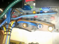
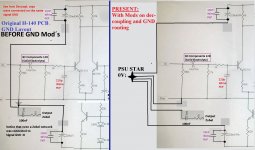
Each H-140 Clone PCB got 14 AWG wire on GND and on OUTPUT +/- 40V. The rest wires are AC 18AWG " Front-End decoupling and Front-End +/- 41V, Output Zobel.
Thick wires have very thick insulation(BLUE ones)
Added a Pic. with mods, best explanation:
Yes about the integrated sound-card on Dell OPT. 780, i feel like when the volume from computer is pushed beyond 45-50%(gain usually below 1), the sound immediately becomes different... same on headphones, same on AMP...
With 50% and more, the gain rises, distortion comes in as op-amps or whatever output stage is causing it.
It could be fixed actually with RIGHT Codecs or some software/driver tweaks... not worth the time imo.
FOR Current source BC550 and 2SC2705, for VAS 2SA1145
Wima FKP, small in size, well looking cap and relatively inexpensive.
WIMA states that FKP-s can be used in oscillator circuits, Timing, High Frequency circuits... so why not
Each H-140 Clone PCB got 14 AWG wire on GND and on OUTPUT +/- 40V. The rest wires are AC 18AWG " Front-End decoupling and Front-End +/- 41V, Output Zobel.
Thick wires have very thick insulation(BLUE ones)
Added a Pic. with mods, best explanation:
Attachments
H140 amps ebay
To date having built some 24 H140 kits HT system and the ground mod works as the last post. caps input feedback etc are all evox MMK 3.3 or 44 uf off board size, changed all transistors so no fakes and used ztx753/653. Grounding is so important so do take time get it right it took me a year to get right hum etc. Both my main speakers are 4 way active with 6 amps in each 3 transformers and each amp has own bridge and cap banks. And it was no point in me saying what was good or not, as it happens my wife has a good set of ears and used her for blind testing it works. Tip make a change and live with it for a few week as things do change and sometimes get better mine did. Speaker cable are short with 8 turns and only 1.5 mtrs long and 1.5 section nothing fancy at all.
To date having built some 24 H140 kits HT system and the ground mod works as the last post. caps input feedback etc are all evox MMK 3.3 or 44 uf off board size, changed all transistors so no fakes and used ztx753/653. Grounding is so important so do take time get it right it took me a year to get right hum etc. Both my main speakers are 4 way active with 6 amps in each 3 transformers and each amp has own bridge and cap banks. And it was no point in me saying what was good or not, as it happens my wife has a good set of ears and used her for blind testing it works. Tip make a change and live with it for a few week as things do change and sometimes get better mine did. Speaker cable are short with 8 turns and only 1.5 mtrs long and 1.5 section nothing fancy at all.
To date having built some 24 H140 kits HT system and the ground mod works caps input feedback etc are all evox MMK 3.3 or 44 uf off board size, changed all transistors so no fakes and used ztx753/653. Grounding is so important so do take time get it right it took me a year to get right hum etc. Both my main speakers are 4 way active with 6 amps in each 3 transformers and each amp has own bridge and cap banks. And it was no point in me saying what was good or not, as it happens my wife has a good set of ears and used her for blind testing it works. Tip make a change and live with it for a few week as things do change and sometimes get better mine did. Speaker cable are short with 8 turns and only 1.5 mtrs long and 1.5 section nothing fancy at all. One strange thing it’s me that turns it down now not the wife, for a simple amp it can work very well, look how long Naim to get it right, cable routes and length come into play, one of the best mods to date is using R core transformer for the supply crossover and a mean night and day stuff I will look at changing all the transformers to r core type
H140 amps ebay
Just one point I have found the more mods you make looking for a better amp and you will get over time the more sensitive they are about are about the quality of the source ie Mp3 they will sound terrible no matter how good the D/A is crap in crap out who said that now, pre amps also have a big effect as well. I did try some Naim NAC42.5 kit from ebay with cap mods evox mmk this did make good improvement to the overall sound they like a low R source the amps that is. So the H140 kit is a fussy thing but get right and it sounds wonderful try down loading some FLAC stuff it is night and day stuff even from a humble PC or lap top
Just one point I have found the more mods you make looking for a better amp and you will get over time the more sensitive they are about are about the quality of the source ie Mp3 they will sound terrible no matter how good the D/A is crap in crap out who said that now, pre amps also have a big effect as well. I did try some Naim NAC42.5 kit from ebay with cap mods evox mmk this did make good improvement to the overall sound they like a low R source the amps that is. So the H140 kit is a fussy thing but get right and it sounds wonderful try down loading some FLAC stuff it is night and day stuff even from a humble PC or lap top
H140 kit ebay
I have rambled on I bit over the last few days, as I remember points it is a fussy thing sometimes it likes to think it’s a radio RFI keep your switch mode PSU PC away from it ( grounding and routing of cables and makes a huge difference how it sounds) . Input to the amp I used balanced 2 core mic cable and grounded the screen back to the star ground between cap bank worked for me. And the power supply use two bridge rectifier’s this keep the centre tap of the transformer out of the ground (note this work for power amps and not pre amps not sure why) if you have long speaker cables (I have HT system) can work as a good antenna RFI back in to the feedback loop it can degrade to sound a lot keep away from mains cables. And the ones buried in the wall that one caused some grief for a few days. Matching the input pair if you them from the batch I have found you tend to get less than 30mv, if above leave on for a few days and it tends to creep down. Setting the bias currant (no such thing as a heat sink to big ) I have found it takes a while up to an hour to get to become stable and take it up in 5ma steps to around 25ma to start if your heat sink is fitted inside and on the small side it will creep up as the norm we adjust the case open the input pair are effected by temp change bias and off set. As the norm I leave on 12 hrs and re check it works for me, then use for a while and re check I use 30ma as the max, my heat sinks are 0.3 deg watt with 3 amps fitted to each and fans from CPU 120mm temp controlled and once you get right just sit back and enjoy
I have rambled on I bit over the last few days, as I remember points it is a fussy thing sometimes it likes to think it’s a radio RFI keep your switch mode PSU PC away from it ( grounding and routing of cables and makes a huge difference how it sounds) . Input to the amp I used balanced 2 core mic cable and grounded the screen back to the star ground between cap bank worked for me. And the power supply use two bridge rectifier’s this keep the centre tap of the transformer out of the ground (note this work for power amps and not pre amps not sure why) if you have long speaker cables (I have HT system) can work as a good antenna RFI back in to the feedback loop it can degrade to sound a lot keep away from mains cables. And the ones buried in the wall that one caused some grief for a few days. Matching the input pair if you them from the batch I have found you tend to get less than 30mv, if above leave on for a few days and it tends to creep down. Setting the bias currant (no such thing as a heat sink to big ) I have found it takes a while up to an hour to get to become stable and take it up in 5ma steps to around 25ma to start if your heat sink is fitted inside and on the small side it will creep up as the norm we adjust the case open the input pair are effected by temp change bias and off set. As the norm I leave on 12 hrs and re check it works for me, then use for a while and re check I use 30ma as the max, my heat sinks are 0.3 deg watt with 3 amps fitted to each and fans from CPU 120mm temp controlled and once you get right just sit back and enjoy
My H-140 boards, both have +5mV after 20mins of running. Bias ~34mA per board.
Tested the amps with high load for a few hours, heat sink gets pretty warm, but not hot... after removing the input signal the heat sink cools down in about 10 minutes.
I just got hands on Creative SB0570 Sound Blaster. It is a wonderful update from a PC intergrated soundcard
For now, re-wiring amp boards as Ian Finch suggested. Going to use twisted wires for +/-/ground to each board.
That's a good result if the cover had been in place before testing. The location of the bias controller transistor means there is only air coupling to the output transistors temp. so bias setting must be carefully considered and done as close to final operating conditions as possible to ensure safety. Mostly, it works out fine but I have seen more than one amplifier killed by wrong layout, oversize or no case, small heatsink etc. The original used the aluminium case as heatsink, and there were fewer problems using that as part of the compact, integrated design in which heat circulated better than standard DIY assemblies.
That soundcard seems to be an excellent bargain. 'Good specs and features too, for a ~30 USD product. 'Hope you found a nice, quiet slot for it and continue to enjoy
That soundcard seems to be an excellent bargain. 'Good specs and features too, for a ~30 USD product. 'Hope you found a nice, quiet slot for it and continue to enjoy
First of all, i finished yesterday my last huge modification to the H-140 boards.
I went from NCC 200 schematic to NAIM NAP-140 schematic:
1) Input resistors changed(4.7k and 22k now)
Took out BC550 CSS and replaced it with MPSA06.
Changed TIP41C and 42C drivers to MJE243 and MJE253
Now MPSA06 in placed = more collector to emitter voltage. It gave me a chance to rise FRONT-END regulated psu lines from 41V to 43.5V.
Replaced avondale VBE output transistors to original MJE15003 and MJE15004.
I get an offset now after 20min (1 board 16mv / 2nd board 12mV)
What is really good news, i got now rock solid BIAS Drift is so small and it stabilized really quick.
Thats it, there is possibility i lost the oscillations. Sound is good so far
EDIT: i had few buddies yesterday here with their FRS8-8ohm speakers(90CM long needle) attached to my AMP, they sounded wonderful, except highs were strange, but its common to FRS8 Visaton speakers.
I was blown away that how good they are playing in small room, even the bass was coming quite clearly.
So, we took FRS8 needles to different place, apartment were the room was 2x bigger.
Played them there, it was awful... how the bass was so full of time lagg(FRS8), they have been beaten by russian low-end 4 inch 2-way speakers
I went from NCC 200 schematic to NAIM NAP-140 schematic:
1) Input resistors changed(4.7k and 22k now)
Took out BC550 CSS and replaced it with MPSA06.
Changed TIP41C and 42C drivers to MJE243 and MJE253
Now MPSA06 in placed = more collector to emitter voltage. It gave me a chance to rise FRONT-END regulated psu lines from 41V to 43.5V.
Replaced avondale VBE output transistors to original MJE15003 and MJE15004.
I get an offset now after 20min (1 board 16mv / 2nd board 12mV)
What is really good news, i got now rock solid BIAS
Drift is so small and it stabilized really quick.Thats it, there is possibility i lost the oscillations. Sound is good so far
EDIT: i had few buddies yesterday here with their FRS8-8ohm speakers(90CM long needle) attached to my AMP, they sounded wonderful, except highs were strange, but its common to FRS8 Visaton speakers.
I was blown away that how good they are playing in small room, even the bass was coming quite clearly.
So, we took FRS8 needles to different place, apartment were the room was 2x bigger.
Played them there, it was awful... how the bass was so full of time lagg(FRS8), they have been beaten by russian low-end 4 inch 2-way speakers
Last edited:
It lives, kinda
So after a lot of other stuff going on finally I have my amp boards working, well one of them. The transformer is a 550VA 0-30, 0-30 from RS comp, thanks to a friend. This is currently wired as 30-0-30 and feeding a simple bridge and cap board. It's not too pretty right now, haven't been able to find the wire I want, but the first channel is working. Offset is about 6mV without any attempt to choose transistors in the LTP, I'm happy with that. Bias sets up smooth and with little apparent drift though more careful measurement is really necessary before I'll consider it good enough. It amplifies and sounds good as is though hopefully some more effort will improve it from the raw version it is now. I notice that TR4 and TR6 seem to run hot, not sure if that is ideal or beneficial for long life, they say 2SB647 and 2SD667 on them if that is to be believed. I have 2SC5171/2SA1930 I could sub for them, they are TO220 so I could also fit small sinks. Good move? I think I have some ZTX/653/753 at home but I'm about 5 weeks away from another visit and there's nothing at all available here in the desert.
I'm not sure if it's oscillating anywhere, seems stable enough. I've made no changes to the build and I'm just using cheap multi strand speaker cable, about 2.5m long to Tannoy 604 speakers, no obviously bad effects.
I think it could use a soft start, the capable transformer and 20,000uF in each leg would be quite a strain on occasions.
I'll finish up the other channel and then see how it sounds with them both running
Martin
So after a lot of other stuff going on finally I have my amp boards working, well one of them. The transformer is a 550VA 0-30, 0-30 from RS comp, thanks to a friend. This is currently wired as 30-0-30 and feeding a simple bridge and cap board. It's not too pretty right now, haven't been able to find the wire I want, but the first channel is working. Offset is about 6mV without any attempt to choose transistors in the LTP, I'm happy with that. Bias sets up smooth and with little apparent drift though more careful measurement is really necessary before I'll consider it good enough. It amplifies and sounds good as is though hopefully some more effort will improve it from the raw version it is now. I notice that TR4 and TR6 seem to run hot, not sure if that is ideal or beneficial for long life, they say 2SB647 and 2SD667 on them if that is to be believed. I have 2SC5171/2SA1930 I could sub for them, they are TO220 so I could also fit small sinks. Good move? I think I have some ZTX/653/753 at home but I'm about 5 weeks away from another visit and there's nothing at all available here in the desert.
I'm not sure if it's oscillating anywhere, seems stable enough. I've made no changes to the build and I'm just using cheap multi strand speaker cable, about 2.5m long to Tannoy 604 speakers, no obviously bad effects.
I think it could use a soft start, the capable transformer and 20,000uF in each leg would be quite a strain on occasions.
I'll finish up the other channel and then see how it sounds with them both running
An externally hosted image should be here but it was not working when we last tested it.
Martin
I love that tiny heatsink.
It looks like it was designed for this duty
I would use a soft start. I do for all transformers >80VA. (i.e. 100VA & 160VA use T500mA).
That allows close rated fusing, rather than the enormous fuse that is required when direct on line starting is implemented.
There is also room to add in a mains DC blocking cap bank.
Unbundle the neat parallel wiring and replace with twisted pairs. You can bundle twisted pairs and retain much of the interference rejection. (Cat5 & 6 use bundled twisted pairs). AND twist your mains wiring.
Last edited:
Yah, ya think?
It is bolted to the floor of the case, for whatever that might be worth. I ran about half an hour of disco thump thump through it and though it certainly got warm it wasn't unbearably hot.
If I can find bigger next time I'm home I'll change them, maybe add a copper heat spreader too.
As a guide how many mm^2 at what deg C/watt would be advisable for such a build?
I always recommend double the Nat Semi guide value.
eg
for a +-34.5Vdc supply with Ta=25°C and 8r0 loading the graph, p14 max Heatsink Thermal Resistance, shows 3C/W for one chip.
for two chips one would use 1.5C/W following their guidance.
I say use 1.5C/W for one chip and use 0.75C/W for two chips.
I was in the middle of testing a pair of chips for active speaker duty.
The test signal was 1kHz and the two chips were set to give 2W from the bass amp and 1W from the treble amp.
I left it running on a ~1.1C/W sink and when I came back after a cuppa (about 20minutes), the chips were too hot to touch, well over 60°C (Ta~19°C). Even the sink next to the chips was too hot to hold my finger on for a couple of seconds. The total average output was ONLY 3W !!!!!
If your amplifier is using a similar 60 to 70mA quiescent current and running on similar supply voltages, one would expect similar dissipations.
I had not used the Nat Semi guide as a universal ClassAB heatsink tool, but your question made me think.
Last edited:
Apologies I responded without seemingly seeing all of your first response. But to answer your latest, many thanks a useful pointer and have found a good read on this at Rod Elliotts website. I'm more used to forcing air past large vacuum tubes and measuring the back pressure than moving the heat away silently
The rest of amp so far is a bit of a lashup for sure. The only wire I could find was far to HD to consider twisting, well I could for the mains feed. That needs a boot and I'll swap the raw socket for a filtered one as well. I'll do the soft start next time I'm home to get some bits. Without it even a 5A pops on occasion.
I don't recognise the term "mains DC blocking cap bank" whazzat?
Thanks
Martin
- Home
- Amplifiers
- Solid State
- NAP-140 Clone Amp Kit on eBay