Hi! This is my first post and I’m coming in full speed. Some years ago I’ve build the Giesberts HEXFET amp (elektor). I’m very happy with its performance. I think it has a quite clear sound overall, although I had the usual problems with oscillations, burned HEXFETs and resistors going up in flame! But I was always able to solve my problems. Mostly by replacing components of the output stage, along with some luck 😉
But now I can’t find my way out! A year ago the left channel decided to blow my SEAS speaker. I replaced all the burned up resistors (don’t remember which) along with all the transistors and FETs. I turned it on and Boooom! R27 (I think) was gone. I replaced it and turned it on once again, but nothing! I was stuck with 100mA (regardless the setting of P2) and zero output. I rechecked my PCB connections, but didn’t come across anything suspicious! So in despair, I let it be!
This was until some days ago. I really miss my old amp and I want it working again! So I tried to take a look, once again. It only took me about 10 months to find out that my relay had a fault. So bypassing it I gave it another try and guess what… I have sound! Problem solved. Not quite. It is distorted! But it is alive and with a high levels of amplification, meaning that my HEXFETS are just fine. I’m sure of that because I also tried them on the right channel board and went ok. This is what i see:
1. Amp current stuck at ~100mA (instead of 230mA), regardless adjustments of P2.
2. DC offset just fine ~1mV.
3. D1 and D2 stay on after amp goes off for 15sec. on the right working channel but on the left channel they are turned on for more than 40sec.
4. HEXFET’s are ok since they provide hi level amplification.
I’ve read what egberttheone and Zimo did and I’m willing to give it a try too. Although I doubt their mods will do me any good. My amp has loud distorted sound without burning any of the circuit components. Why the hell can’t I change the 100mA current? Is it a failure of T7? This was a working amp for over a 3 year period with daily usage. I’m ashamed to have it laying down dead.
Anyway my equipment is only a digital millimeter and an analogue current meter at 500mA. I have also been messing up too much with the PCB and lots of the traces are “replaced” by wires. So components are not easy to go in and out. I’m so close but still so far! Sorry for my English and my long post. Just wanted to give you a solid background of my situation. Won’t be checking in for 2 or 3 days cause I’ll be on a trip.
Thank you for your time!
Attachments
NICE AMP....
may be trimmer is gone and or R19 ..... also you can e mail me privetly and take a look at it in my lab together
regards sakis 6944879399
may be trimmer is gone and or R19 ..... also you can e mail me privetly and take a look at it in my lab together
regards sakis 6944879399
Check the fuses.
This amp producing sound even if one of the fuses is broken,
but distorted sound, only one half wave going to output.
This amp producing sound even if one of the fuses is broken,
but distorted sound, only one half wave going to output.
Check one more time T13, and F2.
If R27 is broken, it means that gate to drain of the T13 was be shorted.
Stability of this amp also depands from the value of the fuses,
with F4A or F5A, resistance in source is smaler, and amp became
more stable.
If R27 is broken, it means that gate to drain of the T13 was be shorted.
Stability of this amp also depands from the value of the fuses,
with F4A or F5A, resistance in source is smaler, and amp became
more stable.
This amp caused troubles to many diyers. Read these threads, it might help you:
http://www.diyaudio.com/forums/showthread.php?s=&threadid=61991
http://www.diyaudio.com/forums/showthread.php?s=&threadid=89526
http://www.diyaudio.com/forums/showthread.php?s=&threadid=61991
http://www.diyaudio.com/forums/showthread.php?s=&threadid=89526
Thanks for all your replies! Just got back and I am glad for your interest to my problem. Here are some quick replies for you too.
sakis >>> R19 and trimmer P2 seams fine. I’m only using PIHER trimmers. I wish I could also be proud for my matsushita relays, which are currently BOTH dead. Elektor suggested Siemens.
radule >>> I tried both T13 and T12 on the right channel pcb board and worked just fine. I am aware of the situation in which distorted sound is produced due to a broken fuse. But I didn’t knew that the fuse value has such a great effect on the resistance in source. However I’m not sure I want to go so high.
Juma >>> Before I post I read both threads that you mentioned thoroughly. But I was hoping to a more "magic" solution!
It seems there is only one way to go on. Replace T7 (maybe reason for weakness of current adjustment) along with T8,T9 (just to be safe) and T10,T11 (may have caused earlier R24,R27 explosions) Apply the suggested changes from the elektor revision of 2002 (DC Protection for the IGBT Power Amp by E. Potters, 024029-1).
I’m also thinking of 6.8V/1W Zener to protect HEXFET’s as egberttheone did. Do you think I could leave them on permanently? Will they degrade sound performance?
So I’m going to get all i need and see what i can do. This is going to be tricky since my right arm is in cast (2 broken bones). But this is not going to stop me, although it may slow me down a bit. Any thoughts till then are welcomed. I thank you all.
I Fixed it, FINALLY.
 Hi! My arm is free again, after 6 months of immobilization. So last night I tried to continue my work on this hexfet amp. I started by replacing resistors and caps as suggested by elektor mag. and other members from this forum. Placed some decoupling caps, changed fuses to 5Amps, replaced trimmer P2 and T7 and R3, R4 to 33ohms. But while I was soldering the 20K resistors to the collector of T8 and T9, I FOUND IT.
  My PCB after a lot of part replacements lost a lot of traces. So my circuit slowly transformed, into a point to point connection. Something went wrong during that and I couldn’t find. It took several months but I saw the base of T7 connected to feedback loop (where R25,R28,R30,R31 meets)
  I stopped everything, fixed that trace and I powered up the amp…
  220mA and 4mV to output! FINALLY …waited 20~30 minutes and connected speakers… IT WORKS! 😀 Cannot believe I was so stupid and BLIND before.
I am not sure what this connection did to the circuit and which part was “cancelled”. I mostly get it, but not quite sure. Any comment on that is welcomed. Anyway… Although it works now I will complete all the following mods to both circuits.
F1, F2 = 5A Fuse
100nF decoupling caps
27N over R31
20kohms resistors from collector T8 & T9 to ground
R3, R4 to 33Oohm
R20 to 1k8
R17, R18 to 390ohm
R25, R28 to 22ohm
R26, R29 to 120ohm
Furthermore I will place heatsinks on T8 and T9… They get extremely hot even with no signal applied. Probably they are oscillating… Also BOTH transformers make a slightly audible sound. That has no effect to output, but it wasn’t there some time ago. 😕 Any ideas on what caused that? Or is it just random. Still… both of them simultaneously? Will post again with the results, but not to soon. I plan to listen to it while I’m working on my other amp project. Here are some pics whith my mistake! The second one is a moving gif. Check it out.
Hi! My arm is free again, after 6 months of immobilization. So last night I tried to continue my work on this hexfet amp. I started by replacing resistors and caps as suggested by elektor mag. and other members from this forum. Placed some decoupling caps, changed fuses to 5Amps, replaced trimmer P2 and T7 and R3, R4 to 33ohms. But while I was soldering the 20K resistors to the collector of T8 and T9, I FOUND IT. My PCB after a lot of part replacements lost a lot of traces. So my circuit slowly transformed, into a point to point connection. Something went wrong during that and I couldn’t find. It took several months but I saw the base of T7 connected to feedback loop (where R25,R28,R30,R31 meets) I stopped everything, fixed that trace and I powered up the amp… 220mA and 4mV to output! FINALLY …waited 20~30 minutes and connected speakers… IT WORKS! 😀 Cannot believe I was so stupid and BLIND before. I am not sure what this connection did to the circuit and which part was “cancelled”. I mostly get it, but not quite sure.
Any comment on that is welcomed. Anyway… Although it works now I will complete all the following mods to both circuits.F1, F2 = 5A Fuse
100nF decoupling caps
27N over R31
20kohms resistors from collector T8 & T9 to ground
R3, R4 to 33Oohm
R20 to 1k8
R17, R18 to 390ohm
R25, R28 to 22ohm
R26, R29 to 120ohm
Furthermore I will place heatsinks on T8 and T9… They get extremely hot even with no signal applied.
Probably they are oscillating… Also BOTH transformers make a slightly audible sound. That has no effect to output, but it wasn’t there some time ago. 😕 Any ideas on what caused that? Or is it just random. Still… both of them simultaneously? Will post again with the results, but not to soon. I plan to listen to it while I’m working on my other amp project. Here are some pics whith my mistake! The second one is a moving gif. Check it out.An externally hosted image should be here but it was not working when we last tested it.
An externally hosted image should be here but it was not working when we last tested it.
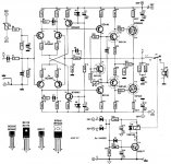
Please forget C50 ( it is for my simulations ).
BD135 -----> BD139
BD136 -----> BD140
Best regards
ED
BD135 -----> BD139
BD136 -----> BD140
Best regards
ED
Oh ! I forgot to say....
The numbers of components are diferent from original Elektor article - September/1995 issue - but not the circuit. In orange color there are the modifications from Elektor - April/2001-pg.58 "Crescendo Millenium Edition" issue. Not valid to R20 and R21 on "my" circuit because it not uses IGBT as output transistors.
The numbers of components are diferent from original Elektor article - September/1995 issue - but not the circuit. In orange color there are the modifications from Elektor - April/2001-pg.58 "Crescendo Millenium Edition" issue. Not valid to R20 and R21 on "my" circuit because it not uses IGBT as output transistors.
Attachments
Hi Eddelarue,
As I can see you are using the schematic of the IGBT amp and not from the Hexfet amp am I right?
As I can see you are using the schematic of the IGBT amp and not from the Hexfet amp am I right?
meanman1964 said:Hi Eddelarue,
As I can see you are using the schematic of the IGBT amp and not from the Hexfet amp am I right?
Hi meanman1964 ,
Yes, you are rigth.
This configuration works very well too.
Is the output wattage the same as the IGBT?The IGBT has 90Watts how much is your version?
Patrick
Patrick
meanman1964 said:Is the output wattage the same as the IGBT?The IGBT has 90Watts how much is your version?
Patrick
This version is the same as the original Elektor - september/1995 issue. I just modified the output transistors. I use power mosfets - IRFP240 and IRFP9240. For this application, they differ from original IGBTs basically on maximum drain current of Pchannel device (GT20D201=20A and IRFP9240=12A ) and the maximum power dissipation (GTs=200W and IRFs=150W ). I believe that IRFs works as the same in this amplifier as IGBTs works without losses. If you want, you may use two pairs os this mosfets in paralleled mode. I didn´t this yet.
meanman1964 said:Did you make your own PCB and can you make a layout of this board for two output pairs?
No. Some years ago I made the pcb from original article ( that uses IGBT ). Do you have it ?
I do have the original layout on Elector cd but never made PCB's myself maybe there is someone who can redraw the layout for use of two pair of output fets
this scheme does not need the Zener diode to protect the gate of the fet?
how this protection to avoid damaging the gate of the fet ?.
how this protection to avoid damaging the gate of the fet ?.
meanman1964 said:Did you use the IRFP240 and IRFP9140 fets aswell?
Well i only did the changes i mentioned. I use the original hexfets. It works just fine, with no problems, for almost a year now. If you get the parts right it has no reason to oscillate.
Interesting mods EDDELARUE. Although i prefer to stick with the original design using IRF540 and IRF9540. I cannot afford to upgrade my PSU.
Beto said:this scheme does not need the Zener diode to protect the gate of the fet?
how this protection to avoid damaging the gate of the fet ?.
I don't think that a Zener diode is necessary. I'm afraid that it may degrade sound quality, but I'm not sure.

- Home
- Amplifiers
- Solid State
- HEXFET amp - please help me fix it.