Well, I saw that too, and thought you did it mainly for simplicity, stacking all the LEDs in one string, which saved you some resistors and dissipation, besides the clean GND issue (which I also think is important).roender said:"Why is the current source Q17,D8 and R20 connected to the anode of D17 ?
That's a very good question! You are the only one who see that and ask about reasons.
The firs stage is a class A stage and I like to have symmetrically currents in every class A stage I design, with as little as possible return currents to ground, to keep the zero reference clean.
- Klaus
KSTR said:Well, I saw that too, and thought you did it mainly for simplicity, stacking all the LEDs in one string, which saved you some resistors and dissipation, besides the clean GND issue (which I also think is important).
- Klaus
Hi Klaus,
The frontend PSU has the same load on both rails and also load symmetrically the rectifier bridge and transformer. It is the only way I know to achieve low EMI injected back in the front stage.
Mihai
Hi Mihai,
I'm completely with you, on these topics. I usually (for ie measurment electronics) go even further than that, by making each rail in itself completely symmetric, after the individual diode bridges, with resistors and common mode and/or differntial mode chokes in both the positive and the negative leg of each individual rails, sort of symmetrical CRC/CLC filtering. Also, I use identical regulators and layouts for both rails (that is, *not* complementary parts or layouts). Each rail circuit is an exact one by one copy of each other, in all details. Sometimes I even use seperate xformers hooked up in a fashion that balances coupling capacitances.
The GND connection is constituted right at the load, not in the supply. And, like you do, I like to use shunt regs (though this is not always an option, depending on allowed power dissipation and efficiency issues). All this brought me a big step forward to get rid of any HF/EMI hash from the mains line (and vice versa, also, especially when I degenerate the primary side of the xformer with chokes/filters/resitors, when this is feasible). Supplies like this almost behave like a battery from an outside world isolation point of view, except for a little capacitive coupling at very low frequencies where it is not a problem.
For power amps, one can split the output L//R in two halves, one at each line (wether it be GND or not) with small caps (a few pF) right at both points to the metal chassis, after the L//R (viewn from speaker side). This keeps common mode speaker line EMI away from the output.
- Klaus
Roender, This amp design of yours is one I would very much like to build. Anyway someone could get the pcb's made. I would be glad to do the Group Buy for this project. Anyone interested in some boards from this nice project please express interest.
Would it be to difficult to expand the output potential a little further to perhaps 150 watts in 8 ohms. Tad
Would it be to difficult to expand the output potential a little further to perhaps 150 watts in 8 ohms. Tad
KSTR said:
For power amps, one can split the output L//R in two halves, one at each line (wether it be GND or not) with small caps (a few pF) right at both points to the metal chassis, after the L//R (viewn from speaker side). This keeps common mode speaker line EMI away from the output.
- Klaus
Hello Klaus,
Can you be more specific please?
Thanks,
Mihai
Hi,
in case Mihai gives his ok (and this would be mandatory for me to participate), and a group buy can be sorted out then I'm in for a stereo set.
Mihai, I'm lost: what is the mechanism your CS-references don't pollute the ground? Isn't finally every tiny bit of charge returned to ground?
Klaus, this HF that seems all too easily pass through any psu-arrangement I tried really drives me crazy. In this case for a phono pre. I would use batteries if I haven't found the sound from batteries too lush.
I'll make a thread for this in a few days when I sorted out some things. Sorry Mihai, I keep quiet now...
Rüdiger
Spkr line RFI filter
Mihai, pls see attachment. The importing thing is that it must be RF-proof, one needs to build the output L//R into a shielded box and one must use feedtrough-capacitors (like these), otherwise it's not completely efficient. This also implies a completely RF-proof metal case in general, and also similar input filtering (signal inputs and mains input). To really make it RF-proof is a lot of work, and not everybody will need this level of protection.
The amp must be able to handle the load capacitance, of course.
- Klaus
roender said:Can you be more specific please?
Mihai, pls see attachment. The importing thing is that it must be RF-proof, one needs to build the output L//R into a shielded box and one must use feedtrough-capacitors (like these), otherwise it's not completely efficient. This also implies a completely RF-proof metal case in general, and also similar input filtering (signal inputs and mains input). To really make it RF-proof is a lot of work, and not everybody will need this level of protection.
The amp must be able to handle the load capacitance, of course.
- Klaus
Attachments
Hi Denis,DRZ1 said:Another question, why not connect the power Transformer center tap directly at the star ground point ?
from a RF interference point of view, a center tapped transformer is a bad thing. The circuit ground is directly coupled to the mains line through the parasitic transformer capacitance. This is especially worse with cheaper toroidal transformers. It can be handled with a electrostatic shield between primary and secondary side, and/or with xformer styles that have less capacitive coupling, ie UI-core xformers with completely seperated windings. Avel-Lindberg has small toriods with a sectoral winding technique (windings not on top of eachother), which are quite good w.r.t. coupling and still have the properties of toroids (if one considers these properties as a good thing, which I personally don't do. I like good UI-style better).
- Klaus
My question was not concerning RF interferences. I'm not shure Mihai make this connection like this for that reason.
But for RF subjet , i wil use semi-toroidal or spilt pack Transformers for the drive section, specially because they don't have capacitive coupling between primary and secondary windings.
But for RF subjet , i wil use semi-toroidal or spilt pack Transformers for the drive section, specially because they don't have capacitive coupling between primary and secondary windings.
Be very carefully with these industrial transformers.Most of them have high magnetic strayfield and is NOT suitable for audio purpose.
Try Plitron for audio or similar....for audio.
The magnetic core and windings have different stages of treatments comparing with industrial xformers.
I have some bad experiences with these.It was needed to wind again transformers but this time with special treatment.A really pain in the a##.
I'll never try again industrial transformers in any audio equipment.
Onvinyl said:Hi,
in case Mihai gives his ok ... I'm in for a stereo set.
... what is the mechanism your CS-references don't pollute the ground? Isn't finally every tiny bit of charge returned to ground?
Rüdiger
Hi Rüdiger
There is no problem if someone else want to start a RMI-FC100 PCB group buy.
Not every current is returned to ground in +/GND/- configuration. Imagine two identically resistors connected in series from + to - with center tap at GND. If + and - voltages are equally in value, there is no current spilled to ground from joint point, but if you don't need to connect that point to ground is even better if you have a non CM signal in +/- rails.
DRZ1 said:hi Mihai
Did you try the compensation pattern discussed at the beginning of the thread?
Another question, why not connect the power Transformer center tap directly at the star ground point ?
Denis
Hello Denis
The PL compensation method bring no improvement in sound fingerprint. The reason is the simple fact that lag capacitors are very small in value to be nocive for this topology.
I don't want to make transformer center tap the main starpoint because I want to isolate bridge/capacitors rectified pulses in one starground and also I have a similar starground for rectified pulses in output stage, isolated from main starground formed at the return ground point from speaker.
Mihai
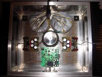
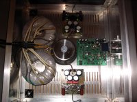
Roender, Have you thought about mouning them vertical on the front wall. Also, On one of the transformer websites they discuss using epoxy to partially mount the screw to the toroid. It is a very nice arrangement. You could also mount the bridge rectifiers to the front and have plenty of space for isolation from the board components. Tad
- Home
- Amplifiers
- Solid State
- RMI-FC100, a single stage audio power amplifier