I have decided to rebuild my defective PS Audio 200 CX amp. Everything will be updated but the power supply (75 volts per very stiff rail). I can use some help with the front end. The drivers and outputs are just up dates, however the front end is all new (MOSFETS). I have included a schematic of my amp so that someone might help. I have incorporated 2 of Nelson Pass idea’s. Bias feedback (from the A40) and global feedback from the drivers, not the outputs (Stasis e series). Please look it over and let me know what you think.
DonS
P.S. All inputs are appreciated!
DonS
P.S. All inputs are appreciated!
Attachments
I don't know what are drawing mistakes and what aren't, but:
- Q6 mosfet is out of polarity
- feedback is 'nearly' global, it is taken from emitter of Q9- this results in high even order crossover distortion
- choice of mosfets is really bad, you need small signal ones, like from IRFDxxx series or IRFx10/IRF9x10 if you stick to IntRect. These you've chosen have too high capacitances.
regards
Adam
Adam, all but the Mosfets are drawing errors. I have fixed the drawing, and changed the devices to 610, 9610's. I thought I might have too large a device there, however I originally designed it with no drivers. I submitted it to Nelson Pass who thought that the VAS would not drive the outputs directly.
The feedback from the emitter resistor is to stabilize bias.
The feedback taken from the driver stage, not the output is global.
The feedback from the emitter resistor is to stabilize bias.
The feedback taken from the driver stage, not the output is global.
Attachments
 good luck!
Thanks, Adam! I will let you know how it goes.
Anyone with more experience than I please join in. That would be about everyone!
There is never a moderator when you need one. Then again no one has ask for the original schematic.
Where are all the guys that normally pop in to help. Am I doing something wrong?
Anyone with more experience than I please join in. That would be about everyone!
There is never a moderator when you need one. Then again no one has ask for the original schematic.
Where are all the guys that normally pop in to help. Am I doing something wrong?
Looking for advice!
Can some of the members that are watching this thread help look for smoked semi's before they happen? I thought this might be a good project for a simple high output amp.
I will provide board drawings and test data to all that help!
Has anyone seen or owned a 200C,X?
How about a ham at Christmas? Or any other holiday?
Help, DonS
Perhaps someone could loan you some simulation software? Sometimes if you are lucky, folks just key the design in at home and simulate it for you and share the results. Perhaps someone is at home(work) with extra time?
I thought there were some freeware simulators? I have not used one yet but I'd be inclined to do so before such a build.
Looks nice. Good luck!
Shawn.
I thought there were some freeware simulators? I have not used one yet but I'd be inclined to do so before such a build.
Looks nice. Good luck!
Shawn.
Re: hmmmmmmmmmm
Well Don S, Retro has a good point. So what cha going to call the new beast?
RetroAudio said:well, it's kinda clear you no longer have a 200CX!
Well Don S, Retro has a good point. So what cha going to call the new beast?
You are right. It is no longer a 200CX. However since the circuit board is toast and some of the semi's are obsolete, what is a guy to do (massive delamination of the board where the factory made it a CX from the original C). The original circuit was not extremely stable either. My design does have the fet diff input and the same output arrangement. The largest differences are lack of a complimentary VAS stage and the elimination of the predrivers
Well the schematic files are labeled A40AB200! This is because of the bias feedback from the emitter resistor (from Pass A40). and the output section of the 200CX (which is the output section of a lot of amps built).
I am open for naming suggestions
DonS
Well the schematic files are labeled A40AB200! This is because of the bias feedback from the emitter resistor (from Pass A40). and the output section of the 200CX (which is the output section of a lot of amps built).
I am open for naming suggestions
DonS
The one negative thing about using this amp for a new design is that it's not fused after the secondary in case oscillation does occur. That's something I'd want if it were my doing. Far be it from me to discourage anyone from doing their thang, but another approach might be to see if you can't recreate the original circuit and maybe seek to improve where you think you can, after all the amp is set up for the uniqueness to that circuit. I understand about the defunctness of it, however often times it's a rather more than difficult thing to turn an amp into something it's not. It's rough enough just restoring the doggone original, talking of course from not knowing how much you know or your background,..but,.I figure if you have to ask then..........
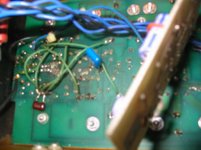
retro, I think that I could possibly redo the amp. However the big hurtle would be the discontinued bias darlinton. It is really a PS Audio 200C,X if the outputs are not the original 2SA909, 2Sc1586's nickel plated solid copper cased Sanken's? The board cannot be reused, and board redesign would be complicated. Not imposible though. This would also include a redo of the servo board. I will include the picture of this mess for you to see. Everything in this amp is jumpered to the factor of 10. To me the really unique thing for this amp is it's 10 pounds of copper power/gnd delivery bars. (the circuit's relatively standard, though it is fast). Table for current, no waiting!
I agree that there is no supply current limiting! Which will destroy a speaker faster, oscillation or DC offset? (speaker protection is 8 amps away! it is in the feedback loop though!)
I can tell you, owning this amp since 1985 that every time that I had a problem it was DC offset.
None of this is a personal assault of you comments!
I am not crushing it, simply restoring it. Is a 428CJ engine not a CJ if we change the cam? This is the closest that I can get with an analogy. A cam is the frontend of any engine, it controls all that goes in and out of the engine. Yes there may be other issues with this change, but overall I think this will improve the overall performance of this amp.
Attachments
Mercy sakes alive. Ok, lesson one: ya gotta be resourceful. However, it's my guess you don't want to rebuild anyway and never looked for any parts.
I found the "discontinued" darlington bias units at both Newark and Mouser. There's also some listed on Ebay this very moment, so shame on you! I stopped there, so I'm sure there's more. With that said, your amp is not down and out by a long shot and is redoable. I know cause I have one that needs it, just have not gotten around to it yet. As far as the condition goes, it's all part of amp rebuilding.
Not sure what your problem with DC offset is, only troubleshooting would tell I suppose. There's not a whole lot that will go wrong with a servo but I don't have the amp here to eyeball. I bet there's quite a bit you'd learn from redoing this, but it does sound like you have your heart on your mosfet stuff.
A major part of amp rebuilding effort goes into being Sherlock Holms for hunting parts and is a large part of the fun I have found. You may not have found it so. Even if parts are not available, it's up to you to make a substitution work. That too is part of the amp world, and if you're willing to do a new design, then you should have the ability to retrofit. If a person cannot retrofit, then I'd personally have serious doubts about any new design. Just my take.
End of sermon..... And I took none of your comments as a personal assault,...not even close. This stuff is just way too fun!
I found the "discontinued" darlington bias units at both Newark and Mouser. There's also some listed on Ebay this very moment, so shame on you! I stopped there, so I'm sure there's more. With that said, your amp is not down and out by a long shot and is redoable. I know cause I have one that needs it, just have not gotten around to it yet. As far as the condition goes, it's all part of amp rebuilding.
Not sure what your problem with DC offset is, only troubleshooting would tell I suppose. There's not a whole lot that will go wrong with a servo but I don't have the amp here to eyeball. I bet there's quite a bit you'd learn from redoing this, but it does sound like you have your heart on your mosfet stuff.
A major part of amp rebuilding effort goes into being Sherlock Holms for hunting parts and is a large part of the fun I have found. You may not have found it so. Even if parts are not available, it's up to you to make a substitution work. That too is part of the amp world, and if you're willing to do a new design, then you should have the ability to retrofit. If a person cannot retrofit, then I'd personally have serious doubts about any new design. Just my take.
End of sermon.....
And I took none of your comments as a personal assault,...not even close. This stuff is just way too fun!Let's compare notes
retro, we should compare notes. What is the serial number of your unit. Mine is 0275. I have a copy of the schematic that is hand drawn. I got mine from Paul McGowen. It shows NEC 2SB600, 2SD555 outputs. My outputs are Sanken 2SA909, 2SC1586. Which outputs does yours use? This schematic does not include the servo board or the faceplate led driver board. I have figured out what was on the main board (signal wise) to drive the led board. Does your amp have the DC offset leds? I understand that they were discontinued on later 200's. I also understand that there were at least 3 major revisions to the pcb over the course of production. Did you have your's updated, or was it a CX from the get go.
I said some semi's were obsolete, not unobtainium.
Onsemi has originals or replacements for everything but the matched jfets(vishay 2N5565). However the MPSU95 appears to be a collectors item.
Lets compare notes. maybe I will put the 200CX frontend in. I have changed the layout of the main board to only outputs, drivers, and bias transistors onboard. My frontend is a daughter board above the main. It pulls power directly from the buss bars, unlike the original that pulled from very small traces on the main board. A couple of screws and wires are all it takes to change the whole frontend.
Thanks, DonS
My outputs are the Sankens and my schematic shows the 2SD, etc. units. It also does not even appear to have a servo with it, am not sure what's up. I could find no serial # but if you saw it you'd understand. Somebody got to it before me and did a royal wack job on it. It's not a healthy amp. There are no LEDS either that I can see. I'm not sure what model it is, but it was advertised as being a 200C as I recall. I bought if off Ebay for pretty cheap, so I didn't really care,..and actually still don't....lol! It was also advertised as working but that was a bit of a stretch, but I let it go anyway. It's main purpose was to get rebuilt someday. I also see some effort going into this cause I see some things I'd like doing a bit different, but that's just me.
I'd start by leaving the front end in place, there's nothing really wrong with it. You can of course juggle resistor values, etc. and a mosfet front end wouldn't gain much if anything to my way of thinking. That front end is also where an offset adjustment is and perhaps that has been tweaked on and why you may be having problems,..who's to say.
I am running however a very healthy PS Audio 100C now and it sounds good without even having been touched. Actually, I take that back. The previous owner tried some stuff and it too was somewhat of a wack job, but easily corrected. Man, it's clear when some work on amps they get weird stuff off websites and such and will try everything but take an electronics course.
For the darlington bias units, try MPSA13 and MPSA63. This is a perfect example of what I was referring to when finding a suitable sub. I'd also forget what PS Audio did or didn't do and just proceed on your own cause that's where you are anyway. Try making the best of it, and you certainly may take the mosfet route - wasn't trying to be a hindrance or anything.
retro, the subs for bias you suggest are to-92 cased, you would have to epoxy these to the copper rails. They also appear to be lower wattage and voltage devices. mpsu45,95 is a mini? to-220 case.
Led board should me mounted to the back of the front panel next to the power relay. You should be able to see 4 to-92 trannies on this board.
The original schematic was known for DC instability. All amps that when back to PS for service got these servo boards added. Thats the ugly little board in my picture. Even that board has jumpers/cut traces all over the place.
I believe the instablity was from the predrivers. It looks like they drive them really hard. I had one smoked predriver and 3 toasted outputs on the same side, polarity, replaced under warranty. It still functioned though, if you didn't mind over 1 volt DC drift in that channel.
Let me know if you would like any info from me as my amp has only been touched by PS. I am the original owner.
Do you have the 100C schematic? I am not sure how similar those are to the 200C,X. I would be interested in taking a look.
Thanks, DonS
- Status
- This old topic is closed. If you want to reopen this topic, contact a moderator using the "Report Post" button.
- Home
- Amplifiers
- Solid State
- PS Audio 200 CX Revisited