Janusz,
Yes, my board design is single sided. I will try to send you a copy of the tracks and component layout. It is hand painted and etched and hence, may not look pretty.
I got almost all resistors custom made for the Stochino amp. I still have a couple of hundreds left of most values. Wherever possible I have used Silver Mica caps.
janusz said:And one final question about transformers. I got my two 625VA toroids from Harbuch. Unfortunatelly one is humming too much and should be replaced.
G'day
Would that be an Antrim transformer? I am almost about to order a few of these from Harbuch, but I don't like the sound of humming.
Cheers,
Glen
Janusz
Tortech will make 1-offs with no problem, or sell you 1 off the shelf. The one I have being made is 2x40V/400VA, 2x50V/100VA & 2x12V/20VA in the one encapsulated transformer. It is $230+GST. For a 2x40V/400VA alone it is $180+GST, so that should give you a guide. Would be cheaper for non-encapsulated. Just e-mail them with your specs for a quote - tortech@ozemail.com.au
I looked at getting one made by Plitron, but they wanted to charge a US$500 engineering fee just to spec it and come back with a price....guess they don't really sell 1 or 2 at a time.
I used 1N6638 in place of the selected 1N4448. The 1N6638 has VR=150V, trr=4.5ns and seems to be a great swap.
I also changed the input filters - I don't like 50uF of electros in the signal path - I made c1 & c2 2.2uF, R9 470R, R12 4.7k and C24 1nF, and dropped R39. I usually wouldn't modify anything, and apart from the large electros, can't think why I went to the effort. I haven't compared the two input filters in listening tests, but my Stochinos sound good. Maybe one of the gurus on this forum could let me know if I have made a bad mistake doing this.
Janusz - what caps did you use to bypass the electros in the feedback loop?
Smithy
Hi Smithy,
Thanks for the info. 1n6638 looks really good on paper. I've checked my ordinary sources (Mouser, Farnell, DigyKey) and none of them has it. Where did you get it from?
As an input cap I use 10uF/100V polypropylene. It's big but just fits in. I'm not using R39, R9 will be 470 or 1k low noise Vishay (I haven't decided yet), C24 is 680pF silvered mica and R12=R20. These will be either 10k or 8.2k low noise Vishays. I have not decided yet but most likely I'll go for 10k.
D25 and D26 are doubled to reduce distortions and as I said before C22-C23 are replaced with a non-polar Black Gate 220uF/50V and it will be most likely bypassed by 2.2uF Solen or Bennic or ME polypropylene. I have a few of these. These are standard speaker crossover caps.
All the other polypropylenes are WIMA. Filtering electros are bypassed by XION "non-inductive" caps and each the PS rail will be additionally filtered by 680nF "non-inductive" cap in series with 1ohm/15W to the ground. That is supposed to minimize the effect of internal inductance of the big filtering electros. Never tried it before. Main electros will also be parallelled by some larger polypropylene caps: 22uF or 47uF. Small pF caps are 500V silvered mica but in some cases (47pF) I might use polypropylenes.
If the NP (or polarised electos) cap in the NFB is kept and connection with the preamp clean, it may be possible to remove the input cap.
I have also reduced R36 to 3.9 ohms as I have a few of these. Theoretically one should go down to 1ohm to minimize the ringing but I don't think my ears will hear the difference. The coil's inductance will also be reduced to about 2.2uH - certainly I will not go above 3uH. If the amps are to drive safe loads then the coil and R36 can be removed. Apparently the removal of both input and output filters makes audiable difference but I know for sure that removing the NFB cap makes a difference. The problem is to set the offset below 10mV but without a servo circuit it may be impossible.
cheers,
Hi Janusz
Trying to remember where I bought them from (it was over 8 years ago...). I've done a bot of a search and it looks like it might (almost) be obsolete now. Some are still around, but the asking price is US$10-40 each!!! I can't believe they were that price when I bought them - from memory they were less than A$1. I'll have a look around here to see if I have any lying around as I would normally buy more than I needed. If I find any I'll send you some over.
Smithy
Thanks, Smithy.
1n6638 diodes are obsolete. You might have bought them from Farnell as Farnell is a distributor for Microsemi.
One can buy them by thousands I believe at reasonable prices per item from some wholesalers. I found a number of them. But still it will be heaps of money for the lot.
cheers,
1n6638 diodes are obsolete. You might have bought them from Farnell as Farnell is a distributor for Microsemi.
One can buy them by thousands I believe at reasonable prices per item from some wholesalers. I found a number of them. But still it will be heaps of money for the lot.
cheers,
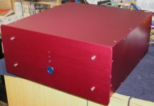
Finally nearing completion on my refit. One amp is finished & assembled. I replaced the output transistors as I needed to change the way they mounted to fit the new heatsink. Interestingly, IR have upped the spec on the IRF640 devices - increased current and higher max Tj (now 175 deg, up from 150) - since I used them about 8 years ago. Anyway, matched the output devices, fired it up and set the bias current to 150mA. Seems to be pretty stable (+/-3mA). Also DC offset seems to be pretty low.
Pic of finished case below - I hand built these with the exception of anodising (the colour is actually cherry red)
Pic of finished case below - I hand built these with the exception of anodising (the colour is actually cherry red)
Attachments
Stochino
Hi Smithy,
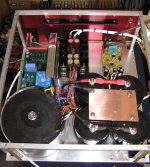
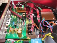
Congratulations on the first module. Very crowded inside.
The middle board looks like a regulated PS, the right one could be a speaker protection board but that is guessing. None looks to me like the original PA board. The main board I presume should be close to the radiator but I do not see anything there.
So what is in the box? What are these boards starting from the left?
cheers,
Hi Smithy,
Congratulations on the first module. Very crowded inside.
The middle board looks like a regulated PS, the right one could be a speaker protection board but that is guessing. None looks to me like the original PA board. The main board I presume should be close to the radiator but I do not see anything there.
So what is in the box? What are these boards starting from the left?
cheers,
Hi Janusz
Not quite as crowded as my last one....I can actually work on this one without pulling everything apart.
I took the photo before putting the amp module in, then last night screwed on the top of the case without taking another photo - I will for the second amp, which will be finished in a couple of days.
The board at the back left is a soft start/remote switch power on (so I can use the push button on the fron panel). This is my own PCB. In front of that is the custom transformer I had wound - potted toroid 2x40V 400VA, 2x50V 100VA and 2x12V 20VA from TorTech. Just in front of the toriod is an IXYS bridge. Front right is 4 x Mundorf 33000uF/80V electros. In the middle rear is a regulator board for the +/-57V regulated rails. Again, one of my PCBs from several years ago - uses LT1085/1033 and HEXFRED rectifiers. To the right of this is a Borbely DC protection, turn on delay. The amp module bolts to the heatsink (cutout in back panel), with the heatsink being a 0.4 deg C/W Fischer unit.
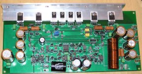
The amp board still uses Caddocks throughout (standard and power), met polprop caps and blackgate caps. As mentioned, I replaced the IRF640/9640s and BD139s as the heatsink mounting method changed for this case.
I made the case from 3mm aluminium panels, 6mm aluminium front panel, with a frame of 10mm square rod and a sub floor of 1.6mm aluminium, which everything mounts on. I drilled and tapped all the holes and countersunk all the screws for a flush finish (except the four cap heads on the front panel). Then I sent all the external panels off to the anodisers....
Two years passed and hundreds of hours later I'm nearly there. Looks heaps better than my previous one.
I should add that the case colour does look really good (even though many will not like it), particularly in its final resting place.
Not quite as crowded as my last one....I can actually work on this one without pulling everything apart.
I took the photo before putting the amp module in, then last night screwed on the top of the case without taking another photo - I will for the second amp, which will be finished in a couple of days.
The board at the back left is a soft start/remote switch power on (so I can use the push button on the fron panel). This is my own PCB. In front of that is the custom transformer I had wound - potted toroid 2x40V 400VA, 2x50V 100VA and 2x12V 20VA from TorTech. Just in front of the toriod is an IXYS bridge. Front right is 4 x Mundorf 33000uF/80V electros. In the middle rear is a regulator board for the +/-57V regulated rails. Again, one of my PCBs from several years ago - uses LT1085/1033 and HEXFRED rectifiers. To the right of this is a Borbely DC protection, turn on delay. The amp module bolts to the heatsink (cutout in back panel), with the heatsink being a 0.4 deg C/W Fischer unit.
The amp board still uses Caddocks throughout (standard and power), met polprop caps and blackgate caps. As mentioned, I replaced the IRF640/9640s and BD139s as the heatsink mounting method changed for this case.
I made the case from 3mm aluminium panels, 6mm aluminium front panel, with a frame of 10mm square rod and a sub floor of 1.6mm aluminium, which everything mounts on. I drilled and tapped all the holes and countersunk all the screws for a flush finish (except the four cap heads on the front panel). Then I sent all the external panels off to the anodisers....
Two years passed and hundreds of hours later I'm nearly there. Looks heaps better than my previous one.
I should add that the case colour does look really good (even though many will not like it), particularly in its final resting place.
Smithy,
did you listen to this one or not yet? If yes, how does it sound comparing to the previous version?
What's the offset reading?
I haven't touch my modules for ages. The first box with two modules needs 20 odd hours of work to be completed so practically it could be done within two weekends but I always have something else to do like working on the new home. My tape deck also need rejuvenation. Sounds like a neverending story.
cheers,
Janusz
Haven't had a chance to listen yet - like you it's hard enough finding time to complete the amps, let alone listening...
I quickly measured the offset last night and it was a lowish 6-7mV (Stochino measured 32mV on his). I did match all transistors when I built it years ago, but I don't remember what the offset was back then. I'm going to fire it up again tonight to take a few more measurements and do a final check before some listening tests, so I'll report back.
Measured offset again tonight and it is sitting around 6mV, which is good. Connected it up and away it went. Need to listen for a while to reveal any differences from the refit/upgrade, but it did sound great (again). I'm running them through Dave Ellis' 1801b and also Dynaudio Finales
Re: best N-P high voltage and power matches
Try IRFP9240 and IRFP340 if you can find the latter. IR seems to have obsoleted a number of their older IRFP series FETs, which is a pity, because they have not replaced all of them by the newer N versions, or the N versions are not good complements. There are droves of N ch ones available still because these were used in far greater numbers than the P ch counterparts. Currently IXYS seems to offer the best selections to chose complementaries from.
janusz said:Hi,
There is also not a great problem to find a few good N-P matches for use at lower voltages and powers. The problem is if one needs higher (120V plus) and power (over 100-150W per device). So the question is:
what are the best higher voltage/power N-P matches available on the market today?
cheers,
Try IRFP9240 and IRFP340 if you can find the latter. IR seems to have obsoleted a number of their older IRFP series FETs, which is a pity, because they have not replaced all of them by the newer N versions, or the N versions are not good complements. There are droves of N ch ones available still because these were used in far greater numbers than the P ch counterparts. Currently IXYS seems to offer the best selections to chose complementaries from.
smithy666 said:the colour is actually cherry red
Lovely case, i've added the image to my collection, Smithy.
Very pretty on the inside too.
Who dare say Aussies lack fancy taste, mate ?

Originally posted by steevo I have been testing my stochino amp... using square and sine waves up 100khz
I wonder if anyone has noticed the part I have emphasized above. high power testing with HF square waves is asking for serious trouble unless you take measures in advance.
- If there is cross-conduction, a square wave test at HF can destroy an amp in seconds. Years ago I helped a friend make a Stochino amp, but because we could not get TL431's here, I redesigned the bias network using a Vgs follower. In order to compensate for the poorer impedance of the Vgs follower t HF I bypassed it with a non-inductive foil cap (0.47uF IIRC), to prevent cross conduction because of base current rectification in the driver stage.
- If there is a Zobel network at the amp output, your amp may be working in a MUCH lower load than expected, and in fact very quickly destroy t he Zobel, or itself. In fact, once the Zobel is destroyed, it may oscillate destroying itself by cross-conduction, and it will be difficult to figure out what the real cause of the problem was.
- square waves which are not limited in slew rate, may have a much higher harmonic content than expected, even taking into account input RC filters on amps. This is because driving an amp from a generator means it is driven from a very low source impedance, making the input filter have the maximum possible corner frequency, and given the filter is first order, you may run into NFB loop instability problems. The instability itself may not be terrible - for instance, just excessive ringing on the output. But, this ringing may contain frequencies that are far above the ones in theinput signal, hence you rin again into cross-conduction and 'low load by zobel' problems.
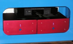
Finally finished the second amp refit. Bias again set to 150mA. DC offset was a bit higher than the other channel, around 23mV (the other channel was 6mV). Anyway, all installed and sounding great. A few pictures follow.
The first photo shows both amps installed in their final resting place. Gryphon Tabu CD player sitting on top.
The first photo shows both amps installed in their final resting place. Gryphon Tabu CD player sitting on top.
Attachments
") Now for the next project
Now for the next project 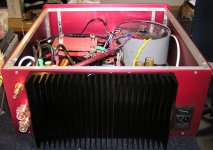
- Status
- This old topic is closed. If you want to reopen this topic, contact a moderator using the "Report Post" button.
- Home
- Amplifiers
- Solid State
- Giovanni Stochino Power Amp