This my reasoning and logic behind why the Amp should be able to run at full power.
The maximum total power that can be dissipated by the mosfets is 480 Watts.
Assuming a Mosfet case temp Tc = 80 degrees then they are derated to 60 watts
Per device. (25 = ideal mosfet temp) Total power that can be dissipated is (125-55) x 4 = 240 watts.
Using ohms law the mosfets dissipate maximum power into 8ohms when the output
into the load is about 17.5 volts rms about half the supply voltage. So the maximum power
they have to dissipate is into 8 ohm with a constant sine wave is about 38 watts.
At full power of 100 watts into 8 ohm and output voltage of 28.3 volts RMS the output stage is only dissipating 23.6 watts.
So given my 0.7 degree/watts heatsink dissipating 40 watts the temp rise is 28 degrees.
28 + 25 = 53 deg and a temp difference between the heatsink and Mosfet case of
20 degrees is a worst case I think gives a Tcase = 73 degrees.
So the amplifier should be able drive full power all day long in my view.
The Mosfet will operate up to a maximum of 125 degrees realistically.
Even into 4 ohms the output is required to dissipate 76 watts at 17.6 volts rms.
derating each mosfet to 50 watts per device this gives a total of 200 watts
for the output stage. The mosfet case temp would be 100 degrees in this case.
I admit that driving a square is different and its effect are different on the mosfets
Than sine wave. Although I’m not sure what the effect of 20khz square wave has as opposed to a
20Khz SIN wave.
Hi,
you're logic is flawed.
I just ran a 120W pair @ Tc<=73degC for 80W into 8ohms and it sits right on the SOAR limit for 60degree phase angle load.
The 4ohm load has to be reduced to 24degrees to fit the 73degC SOAR.
If I reduce the Tc to 50degC (the worst out of the set of 4) then 4ohm can go to 38degree phase angle (still not enough to drive a speaker.
But your 116W into 4r7 load @ 10degree phase angle is well inside the 50degC SOAR by a factor of 2.
I need to increase Tc (worst case) to 100degC to bring the SOAR down to the device peak dissipation.
And that I suspect is the problem. The devices are exceeding a catastrophic temperature limit during your high frequency testing, due to a combination of dissipation into the load and cross conduction that is independant of load.
Have you measured the operating rail voltages just before destruction? I could run the model at that PSU voltage and see just how hard you are stressing the devices.
Hi,
using your +-45Vdc for loaded rails, the model shows 165W into 4r7 at SOAR limit for 80degC. Peak dissipation is shown as about 130Wpk/pr
The power input would be 189W and output is 165W, therefore only 24W is sent to the heatsink (I don't believe this, it's more usually about 60% of output power). This would indicate a sink temperature of just 45degC and a Tc of about 55degC.
There seems to be a small margin (80-55=25Cdeg) at normal frequencies. But the high frequencies probably took the devices over their peak capability, or the sink was hotter than the model predicts.
However, if one substitutes 60% of 165W for sink dissipation, the Tc temperature jumps to about 110degC. That more likely explains the blow up, particularly if there was cross conduction to increase device dissipation a little/lot further.
Giovanni Stochino
Attention moderator on duty, here is the gentlemen's name:
Giovanni Stochino
Cheerio,
Shawn.
Samuel Jayaraj said:Moderators,
You would do well to change the name of the thread to the correct spelling of the original author. This will help when people do a search on the web in general and in this forum specifically.
Attention moderator on duty, here is the gentlemen's name:
Giovanni Stochino
Cheerio,
Shawn.
Otherwise, give the guy a call 
Giovanni Stochino, Via Conte di Carmagnola, 32 I-00176 Roma.
Giovanni.Stochino@Ericsson.com
Giovanni Stochino, Via Conte di Carmagnola, 32 I-00176 Roma.
Giovanni.Stochino@Ericsson.com
Hi Steevo,
I see in another thread that this amp is compared to the Leach amp in terms of having a high slew rate. I have built the Leach on Prof. Leach's boards and am very happy with the performance but am interested in this amp too. I would be grateful if you could e-mail me all the info you have on it.
Thanks in advance
Regards
DavidK
Can anyone help,
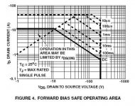
I have been looking at the SOA graph and info for the irf9640 and irf960 and not quite sure how to inertpret the SOA data for the amplifier output stage. Using a worst case supply voltage of 100 volts as recomened by R. Slone ie (2*50volts) for inductvie loads, 100/8ohms = 12.5 amps peak for ech half cycle. divide by 2 for each transistor ouput stage half gives 12.5/2=6.25 so ech transistor has to handle 6.25 amps peak. Drawing a line acros horizontaly so that it intersect the 100 volt line show that it enters a region were the transistor can only withstand this current and voltage for 1ms. Have I interpreted it right. According to the graph VGS has to reduced to less than 20 volts for the transistor tro operate continously without damaging it. Is this correct.
Thanks
Attachments

Hi,
you should do a series of calculations to determine the load line for your loading.
Then de-rate the appropriate SOA for the temperature of the device cases.
Then compare for your operational conditions.
Look up Bensen's spreadsheet and find the reference in there that shows in detail the manual method of what I have quickly described.
If you can't find it, Email me.
steevo said:Using a worst case supply voltage of 100 volts. 100/8ohms = 12.5 amps peak for ech half cycle.
Using both criteria at the same time is wrong.
First step would be to derate for the temperature rise.
Going back to what I said about testing the Giovanni Stochino amp at full over a host of sin and square wave frequncies, I have a quad 306 and the service manual for the unit gives various test at frequencies and powers, one of the test is testing at full power 50 watss into 8 ohms at 100Hz, 2khz, 3khz, 10khz, 20khz and measuring the distorion.
Other tests include 70watts at 4ohms and a test at 25watts into 1ohm at 1khz. If the quad 306 could not perform as specified and failed when driven then it just would not sell and people would not buy it. Going back to my point about the Stochino amp the specification given in the article,
80volts peak to peak at 20khz giving distortion 0.0170%
Power bandwidth of 80Khz.
It should definitely be capable of delivering the performance quoted
I seem to be one of the only people who has built this amp exactly in accordance with the design. I have been using a pair of these for over 8 years and never had a single problem with them. They have been driven hard. I also undertook extensive load testing when first built and as I recall drove them to clipping point with an 8 ohm load attached (which was approximately 120W). I also recall running at this level for minutes. Nothing went zap or bang and the heatsink (or transistors) weren't melting. The heatsinks I used were 0.39degC/W and they are never too hot to touch. My main speakers I use with these are Dynaudio Finales, which are not the most efficient in the world, so the amps run at a reasonable level.
It sounds to me like you have a problem with your transistors, thermal transfer to the heatsink or a construction error.
It sounds to me like you have a problem with your transistors, thermal transfer to the heatsink or a construction error.
Hi Steevo,steevo said:Going back to what I said about testing the Giovanni Stochino amp at full over a host of sin and square wave frequncies, I have a quad 306 and the service manual for the unit gives various test at frequencies and powers, one of the test is testing at full power 50 watss into 8 ohms at 100Hz, 2khz, 3khz, 10khz, 20khz and measuring the distorion.
Other tests include 70watts at 4ohms and a test at 25watts into 1ohm at 1khz. If the quad 306 could not perform as specified and failed when driven then it just would not sell and people would not buy it. Going back to my point about the Stochino amp the specification given in the article,
80volts peak to peak at 20khz giving distortion 0.0170%
Power bandwidth of 80Khz.
It should definitely be capable of delivering the performance quoted
what is glaringly missing from those power specifications is the duty cycle used during the tests carried out by the manufacturer.
Some of these maximum and medium power tests are often carried out at duty cycles around 10%. This is simply to keep the heatsink temperatures down near normal operating temperatures but still see what happens during these sweeps. An alternative may be to specify the maximum temperature of the heatsink and for the service technician to allow time for cooling between runs. He won't like that, it ads to his costs. It's just possible the Quad can supply those power outputs indefinately, but that would be very unusual for cost effective domestic amplifiers.
I agree that amp will not be able to provide those figures for sustained periods thermally. But for a few mins certainly enough to obtain the measurments. The test i quoted were done using a SIN wave I think. I dont know what the duty cycle was for the square wave test.
I will find out.
I will find out.
Hi,
first you need an analogue oscilloscope (20MHz to 50MHz) to see clipping on the output and to see any high frequency oscillation on the output.
Fast digital scopes are rather expensive.
8r0 and 4r7 dummy loads of at least 100W dissipation, preferably more.
Apply the full power signal for only ONE or upto a maximum of TWO seconds and arrange a flick switch to increase and reduce the input signal by 20db. This way you can see the input and output signals on the scope when the amp is just ticking over and go to +20db to adjust the input until the output starts to clip. If this adjustment takes too long flick back and let the amp cool. Then readjust.
Now reduce the input signal until you are 0.05db to 0.1db below clipping. flick back to low power.
Now prepare to take a voltage measurement at full power.
Do all this at 1kHz.
If you are interested in how the amp performs delivering full power at other frequencies, then repeat the whole process for 100Hz and 10kHz.
Change your load and repeat the setting up procedure. and then the measuring process again at your chosen audio frequencies.
If you want to do frequency/bandwidth testing, then do all your testing at the -20db below full power or even a little less (-26db below full power).
I think your 2pair amplifier is only suited to 8ohm reactive loads (on +-48Vdc supply rails) so the 4r7 test to full power must be a resistive load. Do not add any capacitors nor use long speaker cables. For the 8ohm testing you can use parallel cap for checking for instability, many would advise this as normal amplfier be-bugging.
- Status
- This old topic is closed. If you want to reopen this topic, contact a moderator using the "Report Post" button.
- Home
- Amplifiers
- Solid State
- Giovanni Stochino Power Amp