See example below:
An externally hosted image should be here but it was not working when we last tested it.
The error message says 'Can't find definition of model "*****" ', correct? Not, 'Could not open include file "*******" '? And, you haven't made the .include statement a Comment?it'd be great if i could identify why LTspice says it couldn't open the model file, and get that fixed.
If so, that implies it can see the text of the include file, but doesn't recognise the .model line. Again, I would suggest selecting the .model line text in the include file, and pasting it, complete, as a directive in the schematic. If that works, the simulation runs, then I'm not sure what's going on ...
This is my interuptus to inject myself into this learning experience, and to ask the question "Is there an easy way to add model?" most manufacturers have models available like TI for instance. Other users have posted libraries of models . BTW I am a little slow , so go easy on an old feeble minded man...
Regards, Elwood
Regards, Elwood
If you tune into video tutorials you can't do much better than this, Adding Third-Party Models to LTspice IV - YouTube. I learnt something new when watching this, there is usually more than one way of doing things with this program!
Adding a PSpice 3rd party model to a simulation.
Adding and using a PSpice model in LTSpice.
Thanks mainly to Franks link") I had a look at adding a Pspice model to LTspice. As always, I find knowledge is assumed, even after following that video.
I had a look at adding a Pspice model to LTspice. As always, I find knowledge is assumed, even after following that video.
So this part of the tutorial will differ in that I am going to show the pitfalls, and how to troubleshoot it when it doesn't work first time. Please read it all first, then it should make more sense as you try and apply it.
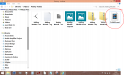
To have a go at this yourself... and I strongly recommend you do, because you learn so much by actually doing something like this and correcting the problems as you go... then you are going to need the model for this example. We are going to use the TLE2072 PSpice model of an opamp and I suggest you first of all get a copy of that from the first attached file in this post. Because it is a non recognised file type I have put it in a zipped folder in order to attach it to the forum.
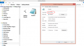
Lets now look at that file before we do anything else. If you right click the file and select <properties> you will see it is referred to as a "301 file". That is the file extension as it appears when downloaded from source.

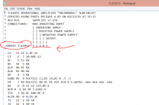
Right click the file again and this time select <open with> and choose notepad. You will see this. Note the name, .SUBCKT TLE2072 and the
pin allocations. We shall refer back to these later.

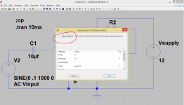
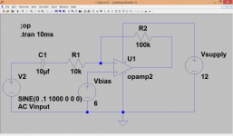
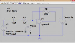
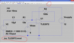
Now we need a simple circuit to try it out on... and you all know how to do that. This is the example we will use. Hint... I would start with the opamp and build the circuit up around that. To select the opamp click <component> on the top line and then double click <opamps>.
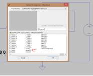
Because we are going to use a 3rd party model, we need only pick the generic opamp symbol. To do this scroll the opamps list to the very end and then pick <opamp2> and place it on the workspace. Hint... before you do that, click the other opamp options and have a look at the text that appears alongside them (my image failed to capture that)
The circuit.

Selecting the opamp symbol.

Selecting opamp2

Build your circuit up to match the example above, and now the fun starts...
(for those that want to jump straight in, the attachment "Adding Models 1" is the .asc file MINUS the opamp. This folder also includes the model file)
At this point you should have the simulation file open and the "opamp 2" symbol placed.

Run the sim and see what happens. You get an error message saying an unknown subcircuit has been called in. So we now need to apply our notepad file of the opamp data to this symbol. Before we do, lets try and make sense of that pin out information I asked you to look at right at the start.
1/ Have the simulation file open in LT.
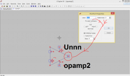
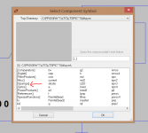
2/ RIGHT CLICK the opamp to open the "component attributes" box and click <open symbol>.

3/ Now if you RIGHT CLICK a node on the symbol you should see how it ties up with the information in the model file. So "5" is actually the output.

4/ Now we need to add the model data to the symbol. Close all open boxes and get back to the basic sim file again. Right click the opamp and give the value box a double click to clear the field and enter the new value of TLE2072. Note how this info matches the .SUBCKT TLE2072 line near the top of the model file data although we enter just the TLE2072 name .

5/ Next we add a spice directive (a .op line) of .inc TLE2072.mod

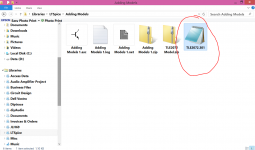
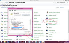
6/ Now run the sim. You should find...... that once again it won't run and returns an error message. What could have gone wrong ? At this point I am assuming that some of you have not been into your Windows control panel and changed the folder view to uncheck the "hide extensions to known file types" box. If so then alter it now.

If you now look again at the model file you will see it now correctly displays its file extension of 301. This was hidden before, and 301 means nothing to LT.

7/ We now need to simply rename the file to TLE2072.mod by simply right clicking and changing the 301 to mod. For some reason W8.1 changes the view to that of a movie but its of no consequence.

At this point, hopefully, your simulation should run.

So there we have adding a Pspice model to LT and working through the steps needed to get it all to work. Hopefully, by showing where and why it didn't work, you have a better idea of figuring out solutions.
I know I've learnt a lot from doing that.
Adding and using a PSpice model in LTSpice.
Thanks mainly to Franks link
I had a look at adding a Pspice model to LTspice. As always, I find knowledge is assumed, even after following that video. So this part of the tutorial will differ in that I am going to show the pitfalls, and how to troubleshoot it when it doesn't work first time. Please read it all first, then it should make more sense as you try and apply it.
To have a go at this yourself... and I strongly recommend you do, because you learn so much by actually doing something like this and correcting the problems as you go... then you are going to need the model for this example. We are going to use the TLE2072 PSpice model of an opamp and I suggest you first of all get a copy of that from the first attached file in this post. Because it is a non recognised file type I have put it in a zipped folder in order to attach it to the forum.
Lets now look at that file before we do anything else. If you right click the file and select <properties> you will see it is referred to as a "301 file". That is the file extension as it appears when downloaded from source.
Right click the file again and this time select <open with> and choose notepad. You will see this. Note the name, .SUBCKT TLE2072 and the
pin allocations. We shall refer back to these later.
Now we need a simple circuit to try it out on... and you all know how to do that. This is the example we will use. Hint... I would start with the opamp and build the circuit up around that. To select the opamp click <component> on the top line and then double click <opamps>.
Because we are going to use a 3rd party model, we need only pick the generic opamp symbol. To do this scroll the opamps list to the very end and then pick <opamp2> and place it on the workspace. Hint... before you do that, click the other opamp options and have a look at the text that appears alongside them (my image failed to capture that)
The circuit.
Selecting the opamp symbol.
Selecting opamp2
Build your circuit up to match the example above, and now the fun starts...
(for those that want to jump straight in, the attachment "Adding Models 1" is the .asc file MINUS the opamp. This folder also includes the model file)
At this point you should have the simulation file open and the "opamp 2" symbol placed.
Run the sim and see what happens. You get an error message saying an unknown subcircuit has been called in. So we now need to apply our notepad file of the opamp data to this symbol. Before we do, lets try and make sense of that pin out information I asked you to look at right at the start.
1/ Have the simulation file open in LT.
2/ RIGHT CLICK the opamp to open the "component attributes" box and click <open symbol>.
3/ Now if you RIGHT CLICK a node on the symbol you should see how it ties up with the information in the model file. So "5" is actually the output.
4/ Now we need to add the model data to the symbol. Close all open boxes and get back to the basic sim file again. Right click the opamp and give the value box a double click to clear the field and enter the new value of TLE2072. Note how this info matches the .SUBCKT TLE2072 line near the top of the model file data although we enter just the TLE2072 name .
5/ Next we add a spice directive (a .op line) of .inc TLE2072.mod
6/ Now run the sim. You should find...... that once again it won't run and returns an error message. What could have gone wrong ? At this point I am assuming that some of you have not been into your Windows control panel and changed the folder view to uncheck the "hide extensions to known file types" box. If so then alter it now.
If you now look again at the model file you will see it now correctly displays its file extension of 301. This was hidden before, and 301 means nothing to LT.
7/ We now need to simply rename the file to TLE2072.mod by simply right clicking and changing the 301 to mod. For some reason W8.1 changes the view to that of a movie but its of no consequence.
At this point, hopefully, your simulation should run.
So there we have adding a Pspice model to LT and working through the steps needed to get it all to work. Hopefully, by showing where and why it didn't work, you have a better idea of figuring out solutions.
I know I've learnt a lot from doing that.
Attachments
-
TLE2072 Model.zip661 bytes · Views: 226
-
 Attributes 2.PNG44.3 KB · Views: 201
 -
 Attributes.PNG44.1 KB · Views: 206
 -
 Basic file.PNG38.3 KB · Views: 188
 -
 Opamp2.PNG22.3 KB · Views: 175
 -
 Select opamp.PNG19.6 KB · Views: 193
 -
 Mod1.PNG38.2 KB · Views: 225
 -
 Model TLE2072.PNG32.5 KB · Views: 182
 -
 301 File.PNG109.9 KB · Views: 206
 -
Adding Models 1.zip1.2 KB · Views: 212
Hi Mooly,
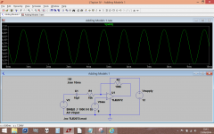
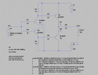
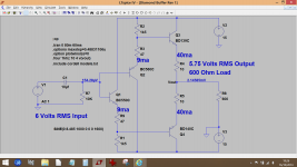
Thanks for this great tutorial, I'm trying to learn LTspice and this is great help. As part of the learning process, I picked a simple diamond buffer circuit from the Internet and tried to simulate it, I could run through the different analysis, FFT, THD, ... and get perfect sine wave at the buffer output.
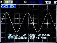
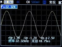
All seemed well, until I actually built the circuit on a breadboard, and I could see very obvious distortion at the crossovers when Rload is around 300R, I changed Rload to 39K and then the output looked OK (attached). I triple checked the connections and quite sure that it's the same as the schematic.
So my question is, what could lead to such difference between the simulated output and measured output. The BJT models are just from Google search, not sure if they're accurate or not.
Thanks and regards.
Thanks for this great tutorial, I'm trying to learn LTspice and this is great help. As part of the learning process, I picked a simple diamond buffer circuit from the Internet and tried to simulate it, I could run through the different analysis, FFT, THD, ... and get perfect sine wave at the buffer output.
All seemed well, until I actually built the circuit on a breadboard, and I could see very obvious distortion at the crossovers when Rload is around 300R, I changed Rload to 39K and then the output looked OK (attached). I triple checked the connections and quite sure that it's the same as the schematic.
So my question is, what could lead to such difference between the simulated output and measured output. The BJT models are just from Google search, not sure if they're accurate or not.
Thanks and regards.
Attachments
Generally there are some differences between the simulated DC condition and the measured ones, but I assumed it's due to difference in beta so didn't really dig into them. (e.g. the simulated output offset is 48mV, the measured one was around 30mV when input was shorted to ground).
OK...
With no load attached what do you measure across the 1 ohms (and so calculate the current). If that is zero or very low it will cause the distortion. If so then try dropping the 1k's to say 820 ohm or 560 ohm. You need to be careful though because the 1 ohms mean that the outputs could suddenly draw a lot of current... destructively so. Perhaps increase those for now to say 220 ohm or so, just to get a feel for what is going on.
Back in a bit...
... but did a stupid thing and reversed the power connections, all the BJTs are dead and 2 resistors on fire ...
That also will not happen in simulation
but you may not recognize that the sim lying to you for quite awhile depending on your expectations if you still see outputs respond to the input stimulus in physically impossible situations that Spice modeling errors allow to run in sim anyway
This is exactly the thing that I am trying to understand, but obviously still trying
BTW I forgot to mention one thing, the original circuit use BD135/136, but since I don't have them and do have a few piece of BC550/560 around - I've used BC550/560 instead, maybe that's the culprit.
Another little trick you can use on the Diamond Buffer is to split each 1k and so make a divider. This allows you to bias the outputs more accurately. This is one I did a few weeks ago.
(Any generic transistors such as you mention should all work OK in circuits such as this)
(Any generic transistors such as you mention should all work OK in circuits such as this)
Attachments
To highlight just how sensitive this is here is your original circuit with two additional resistors added (R10 and R11). In your original the simulation gives nearly 14ma flowing in the outputs. Making those resistors just 1 ohm increase that to 22ma. Make them 4.7 ohm and the current is 65 ma. That's a danger sign that a circuit is going to be sitting on a knife edge and at best a one off and unrepeatable.I suspect it would be vulnerable to temperature change too.
Now lets make the 1 ohm emitter resistors (R7 and R8) into 10 ohms. The range of current in the outputs is now 4.5 ma to 12ma as the new resistors are increase from zero to 4.7 ohms. I would probably go to something like an 18 or 22 ohm for those emitter resistors and then adjust the newly added parts to give your desired quiescent current.
Now lets make the 1 ohm emitter resistors (R7 and R8) into 10 ohms. The range of current in the outputs is now 4.5 ma to 12ma as the new resistors are increase from zero to 4.7 ohms. I would probably go to something like an 18 or 22 ohm for those emitter resistors and then adjust the newly added parts to give your desired quiescent current.
Attachments
- Home
- Design & Build
- Software Tools
- Installing and using LTspice IV (now including LTXVII), From beginner to advanced