Guys I want to learn how to measure amplifier frequency response,gain level ,thermal harmonic distortion, etc of a power amplifier
I don't have a oscilloscope for that. How to measure these data with a laptop?
What are the softwares and tools for that?
Your help is really appreciated!!
I don't have a oscilloscope for that. How to measure these data with a laptop?
What are the softwares and tools for that?
Your help is really appreciated!!
I use Visual Analyzer and REW for that.
Holms works too but you will need a proper interface inorder to not blow up the input of your sound card.
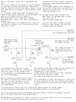
I show such an interface here,
A TEST JIG FOR FINDING ESL STEP-UP TRANSFORMER PARAMETERS
A TEST JIG FOR FINDING ESL STEP-UP TRANSFORMER PARAMETERS
Or Here,
http://www.diyaudio.com/forums/software-tools/212908-exploring-visual-analyser-va-3.html#post3669921
Basically you need a Voltage divider and a Buffer opamp to feed the input of your sound card and just omit the part about the transformer in my example and replace the primary winding with your test load resistor or speaker.
At First I used a common Jfet input opamp (TL072) but since then I have switched to unity gain stable types such as the Lt1007 or equivalent.
You must use a buffer to feed the sound card or else the inputs changing impedance with frequency will give you a slightly false measurement.
jer")
Holms works too but you will need a proper interface inorder to not blow up the input of your sound card.
I show such an interface here,
A TEST JIG FOR FINDING ESL STEP-UP TRANSFORMER PARAMETERS
A TEST JIG FOR FINDING ESL STEP-UP TRANSFORMER PARAMETERS
Or Here,
http://www.diyaudio.com/forums/software-tools/212908-exploring-visual-analyser-va-3.html#post3669921
Basically you need a Voltage divider and a Buffer opamp to feed the input of your sound card and just omit the part about the transformer in my example and replace the primary winding with your test load resistor or speaker.
At First I used a common Jfet input opamp (TL072) but since then I have switched to unity gain stable types such as the Lt1007 or equivalent.
You must use a buffer to feed the sound card or else the inputs changing impedance with frequency will give you a slightly false measurement.
jer
Last edited:
"Basically you need a Voltage divider and a Buffer opamp to feed the input of your sound card and just omit the part about the transformer in my example and replace the primary winding with your test load resistor or speaker.
At First I used a common Jfet input opamp (TL072) but since then I have switched to unity gain stable types such as the Lt1007 or equivalent.
You must use a buffer to feed the sound card or else the inputs changing impedance with frequency will give you a slightly false measurement."
jer
At First I used a common Jfet input opamp (TL072) but since then I have switched to unity gain stable types such as the Lt1007 or equivalent.
You must use a buffer to feed the sound card or else the inputs changing impedance with frequency will give you a slightly false measurement."
jer
Right now I have a local pa amplifier, I want to know the parameters like the,gain level,how to connect it to a laptop?
All programs to do that need some way to generate a signal and read the amp output back into the computer (PC or laptop same principle).
The thing that does this is called a sound card.
If you google you will see that there are different types: there are soundcards that plug into the inside of a PC in an interface slot, there are stand-alone soundcards with USB or Firewire interface to the computer, and then there is the 'soundcard' present inside each computer and laptop which can be connected through the headphone jack (for signal generation) and mic input jack (to read the amp output.
Once you know what you have, you can use many, many different programs to do the tests you want to do.
Many people here use Virtual Analyser, ARTA, TrueRTA REW etc.
And you probablky need to make some sort of interface to make sure you don't blow up the souncard input as noted above.
And, I don't think you can reasonbly do a lot of usefull work without a scope - it's the basic instument to know what goes into and comes out of your amp.
You really need to do some research!
jan
Since you have installed ARTA, read pages 8 and 9 of the ARTA user manual.
You need Figure 1.4 with your PA amp as the D.U.T, but you must insert a 'Voltage probe' between the amplifier output and the soundcard right channel input.
The Voltage probe is shown in Figures 1.5 and 1.6. It's a simple attenuator and protection network that prevents damage to your soundcard.
You need Figure 1.4 with your PA amp as the D.U.T, but you must insert a 'Voltage probe' between the amplifier output and the soundcard right channel input.
The Voltage probe is shown in Figures 1.5 and 1.6. It's a simple attenuator and protection network that prevents damage to your soundcard.
You need about 50:1 attenuation to protect a sound card from speaker output.You must use a buffer to feed the sound card or else the inputs changing impedance with frequency will give you a slightly false measurement."
jer
This could use a 4k7+100R divider giving a 100R output impedance. This is low enough not to need a buffer
Yes the 100 ohm for the bottom resistor will heLp but it will still give you as much as a 15% error for an input impedance of 600 ohms and this gets worse as the frequency is raised.
It is best to use a buffer on the input as this will isolate the sound cards input impedance that it is in parallel with the bottom resistor of the voltage divider.
This assures complete accuracy!
Use this calculator to determine your values,
Voltage Divider
Don't kid yourself as I had already tried this myself and I my curves still came out slanted (when they should have been flat) and incorrect until I started using a simple buffer.
Using the Buffer my curves came out ruler flat as they were supposed too.
jer
Attachments
Last edited:
Most audio circuits are as low as 600ohm!!
In fact it is the standard for Pro audio.
If you want to drive a line with 20Vp-p then yes some opamps will struggle with that.
But it is not an issue a 4Vp-p signal.
Typically most soundcard inputs start clip at anything much over 2Vp-p.
Unless you are using one that is setup for Balanced in and outs.
My Gina 24 card will easily produce a 18Vp-p signal as does my pro audio recording mixer.
Here is some general info,
http://en.wikipedia.org/wiki/Line_level
http://hardandsoftware.mvps.org/sound_card.htm
FWIW
jer
Last edited:
If you mean the 600 Ohm terminated line standard, that was already pretty much dead when I worked in pro audio in the early 80's.Most audio circuits are as low as 600ohm!!
In fact it is the standard for Pro audio.
To quote your Wikipaedia reference:
'A typical line out connection has an output impedance from 100 to 600 Ω, with lower values being more common in newer equipment. Line inputs present a much higher impedance, typically 10 kΩ or more'
The ability for pro audio gear to drive a 600R load seems a legacy requirement, unless it's needed to drive 16 line inputs in parallel.
Balanced mic connections are usually 150R source and about 2K load.
If you want to drive a line with 20Vp-p then yes some opamps will struggle with that.
But it is not an issue a 4Vp-p signal.
Typically most soundcard inputs start clip at anything much over 2Vp-p.
Unless you are using one that is setup for Balanced in and outs.
My Gina 24 card will easily produce a 18Vp-p signal as does my pro audio recording mixer.
Here is some general info,
Line level - Wikipedia, the free encyclopedia
Sound Card
FWIW
jer
Yes, voltage swing into 600R not a problem, I should have been clearer as I meant 'Struggle without excess distortion' Well I wouldn't drive 600R with an ordinary opamp.
I checked the manual for your Echo Gina 24 - it has 10K input impedance. I wonder why you got response errors without a buffer, maybe it has heavy input capacitance ?
Yes, I haven't had many issues with the Gina24 but I have with my motherboard sound systems.
The one I was using when I discovered this issue is the Asrock 990FX Extreme4 mainly.
And I was using a 1k for the bottom resistor thinking that it should have been low enough , but it wasn't.
jer
The one I was using when I discovered this issue is the Asrock 990FX Extreme4 mainly.
And I was using a 1k for the bottom resistor thinking that it should have been low enough , but it wasn't.
jer
Last edited:
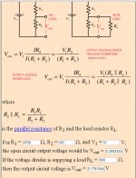
Considering an amplifier that size can produce at least 110Vrms in to 8 ohms I would use a 100:1 division ratio.
This would keep the voltage range well within the capability of most any sound card.
As shown in my example (R1, R2, R3).
And use at least a total divider resistance 10K ohms or greater.
At 10K the resistors would need to dissipate at least 1.2watts at full power.
Using a total resistance of 100k you the would only have to dissipate .12 watts (120 milliwatts) so you could get away with using the much more common sizes such as 1/4 and 1/2 watt types.
I started with a 1 meg and it works just fine as well.
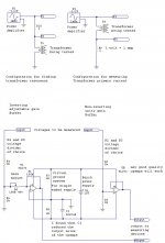
I also employed a trimmer for fine adjustment of the calibration as shown in my schematic.
jer
This would keep the voltage range well within the capability of most any sound card.
As shown in my example (R1, R2, R3).
And use at least a total divider resistance 10K ohms or greater.
At 10K the resistors would need to dissipate at least 1.2watts at full power.
Using a total resistance of 100k you the would only have to dissipate .12 watts (120 milliwatts) so you could get away with using the much more common sizes such as 1/4 and 1/2 watt types.
I started with a 1 meg and it works just fine as well.
I also employed a trimmer for fine adjustment of the calibration as shown in my schematic.
jer
Attachments
Last edited:
In order to use lower resistance type as perviously discussed then the dissipation factor goes up considerably.
Lets say you wanted to not use the buffer, then you would need a bottom resistor of 100 ohms or even less to reduce the error margin.
A 1000 ohm and a 10 ohm resistors would allow for a 100:1 ratio, but, it would also require them to dissipate at least 10 watts of heat.
In this range of resistance you then have lesser range of tolerance for resistor accuracy.
It is just easier cheaper and more accurate to use a buffer and higher values of resistance for your voltage divider.
FWIW
jer
P.S. Use the ones I show in my example and you won't have any problems as long as you include the buffer.
Here is the second part, the buffer section.
R2 and R3 is the resistor divider of your choice.
Attachments
Last edited:
But not PCsMost audio circuits are as low as 600ohm!!
In fact it is the standard for Pro audio.
jer
Normally PC built in AC97 or consumer sound cards are 47k
That may be so.
But I did get inaccuracy's without the buffer as did another DIYer whom has used this method.
This is documented in another similar thread.
There was no question that the input impedance did change with frequency even though it may be in a range of 47K it is not exactly rock solid as per frequency.
Not all sound cards may exhibit this action but most of the ones I have tested in my arsenal did show this problem.
All I can say is try it, YMMV.
FWIW
jer
Last edited:
So voltage divider like this one is needed,Right??
How to Make a Voltage Divider Circuit: 9 Steps (with Pictures)
Also,what is the difference between this oscilloscope?
Use Your Laptop as Oscilloscope
Are both methods the same just by using different techniques?
How to Make a Voltage Divider Circuit: 9 Steps (with Pictures)
Also,what is the difference between this oscilloscope?
Use Your Laptop as Oscilloscope
Are both methods the same just by using different techniques?
- Status
- This old topic is closed. If you want to reopen this topic, contact a moderator using the "Report Post" button.
- Home
- Design & Build
- Software Tools
- amplifier measurements