Yes. The First link is correct as far as the concept goes.
In the second link I have used that software before and it is okay but it is quite limited.
Visual analyzer is much better has more features and it is free.
Another great piece of software is Wave Spectra, it is mainly a RTA but it also has a scope type display for viewing waveform's as well.
It is very fast and works great.
There is a newer version but this one works great as well,
http://www.diyaudio.com/forums/equi...r-analyzing-static-wav-files.html#post1391451
Here is a link to the latest version,
http://www.diyaudio.com/forums/equipment-tools/208866-measurement-advice.html#post2947083
Here is some more stuff,
http://www.diyaudio.com/forums/soft...response-entire-sound-system.html#post2916540
You can start using these right away to get your self familiarized with them and they are all free!!
jer")
In the second link I have used that software before and it is okay but it is quite limited.
Visual analyzer is much better has more features and it is free.
Another great piece of software is Wave Spectra, it is mainly a RTA but it also has a scope type display for viewing waveform's as well.
It is very fast and works great.
There is a newer version but this one works great as well,
http://www.diyaudio.com/forums/equi...r-analyzing-static-wav-files.html#post1391451
Here is a link to the latest version,
http://www.diyaudio.com/forums/equipment-tools/208866-measurement-advice.html#post2947083
Here is some more stuff,
http://www.diyaudio.com/forums/soft...response-entire-sound-system.html#post2916540
You can start using these right away to get your self familiarized with them and they are all free!!
jer
Suppose we want to measure an audio power amplifier 100W RMS with the aid of a sound card.In order to use lower resistance type as perviously discussed then the dissipation factor goes up considerably.
Lets say you wanted to not use the buffer, then you would need a bottom resistor of 100 ohms or even less to reduce the error margin.
A 1000 ohm and a 10 ohm resistors would allow for a 100:1 ratio, but, it would also require them to dissipate at least 10 watts of heat.
In this range of resistance you then have lesser range of tolerance for resistor accuracy.
It is just easier cheaper and more accurate to use a buffer and higher values of resistance for your voltage divider.
FWIW
jer
P.S. Use the ones I show in my example and you won't have any problems as long as you include the buffer.
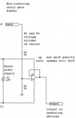
Here is the second part, the buffer section.
R2 and R3 is the resistor divider of your choice.
Can you post schematic diagram using this buffer? (tl072)
I have already posted the schematic in post 17.
It is not any more simpler than this!!!
You just chose a value for R2 and R3 for the voltage division you need.
Use the calculator link I posted in post 9 to help you with the values, it is easier than doing it by hand.
A 100 watt amplifier will produce a 40Vpeak signal and most soundcards are only good for an input voltage of 1V peak or maybe 2V peak.
Some can do more, This you will have to find out for the card that you are using.
So, I would start with at least a 50:1 ratio to be sure that you don't clip the input of your sound card.
If your card can handle up to 4Vpeak then you can use as low as a 20:1 or even a 10:1 division ratio.
It is all about Ohms law when it comes to the power rating of the resistors.
A 10K or even a 100K for R2 is a good place to start for small amplifiers in the 100 watt range and then select the value of R3 for the division ratio that you desire.
100K or greater is a better choice as you can use 1/4 watt or even 1/8 watt resistors for this power range.
The closer you get the values by hand selection and measuring, the more accurate your interface will be.
I used a Trimmer pot for R3 so that I can adjust it for any inaccuracies as I have already shown in post 15.
jer
P.S. There is no output capacitor used in this schematic because most (if not all) soundcard's already have a capacitor on their inputs so it is omitted.
Attachments
Last edited:
- Status
- This old topic is closed. If you want to reopen this topic, contact a moderator using the "Report Post" button.