You can right-click on the .model text and select "not visible". That will get it out of the way. It will be back next time you open the schematic though.
There are many reasons a .model statement may not work. Go to view->Error log and tell us what it says, or whatever error message you were given.
There are many reasons a .model statement may not work. Go to view->Error log and tell us what it says, or whatever error message you were given.
Putting the spice models as directives works, but now I am trying to get the entire power supply to work.
I have already simulated its separate parts and get around the expected -120db. ripple, when I try to put the whole thing together I get anomalous results, in this one I get far more ripple at the output than at the pre-regulator.
Putting those two d.c. sources there works for d.c. operating point but not transient.
rcw
Attachments
This is the version of it that I hung the transformer and two d.c. power supplies off. I was trying to get the d.c. operating point and then the transient output, but it seems this scheme does not work. I you could show me how to model this correctly I would be most grateful.
rcw
rcw
Attachments
This is the version of it that I hung the transformer and two d.c. power supplies off. I was trying to get the d.c. operating point and then the transient output, but it seems this scheme does not work. I you could show me how to model this correctly I would be most grateful.
rcw
Change K1 to 'K1 L2 L3 L4 1' and rotate L3 (not strictly needed).
For the input transformer you have L2, L3 and L4, but your K statement uses L1, L2 and L3. Somehow L1 got into your voltage reference which is why your output voltage is going nuts. L4 should be in your voltage reference and shouldn't be in any K statement.
4.7mH in series with the reference filter makes a series resonator, and blocks filtering except at the resonant frequency. It seems like a mistake?
4.7mH in series with the reference filter makes a series resonator, and blocks filtering except at the resonant frequency. It seems like a mistake?
transformer K shouldn't be 1 it is always strictly less than 1 .999 is fine though
power xfmr have many H Lm - not uH
there are also bias and startup problems - you can't often power your Vref from your regulated supply without some other current path - sometimes provided by real world parasitics - but it is bad practice to rely on such - plan how to get required starting currents
I would leave the trafo K at 1. Otherwise, it will have leakage inductance which will resonate with the rectifiers and cause unwanted effects in the simulation. If the intent was to simulate and design a rectifier, then yes I'd adjust K to give the correct leakage inductance.
In some regulators the pass transistor turns on immediately and in others it must wait for the small-signal circuitry to turn on. In the first case you can power your reference from the regulator output. This is an extremely tricky part of regulator design.
In some regulators the pass transistor turns on immediately and in others it must wait for the small-signal circuitry to turn on. In the first case you can power your reference from the regulator output. This is an extremely tricky part of regulator design.
The 4.7mH. choke and the two capacitors are a notch filter, the components before them a low pass filter.
The capacitor across the top resistor of the feedback divider gives the whole thing unity gain for ac down to around 50Hz.
Since this is essentially a lead compensation capacitor the overall regulator has a very good phase margin, frequency response bellow.
rcw
The capacitor across the top resistor of the feedback divider gives the whole thing unity gain for ac down to around 50Hz.
Since this is essentially a lead compensation capacitor the overall regulator has a very good phase margin, frequency response bellow.
rcw
Attachments
Some time ago I discovered and reported a bug to the "bug report" folks at LTSpice, but they refused to acknowledge it as a bug. The fellow's name I dealt with is Mike Engelhardt.
While doing power measurements on a circuit, I discovered that if the circuit is changed but the power probes are not deleted then replaced on the schematic, the average power computation will be incorrect if the sim is run again. It turns out that you have to remove any power probes after a circuit change, then you must re-place them on the schematic in order to obtain the correct average power.
I normally use PSpice, but have used several SPICE programs, and NONE of them have this issue, except LTSpice.
LTSpice doesn't have any "power probes" that I'm aware of. If you alt-click on a transistor it will plot a trace showing dissipation, but nothing remains on the schematic.
Mike Engelhardt is THE PROGRAMMER of LTSpice. Yes, I know, communicating with these guys can be frustrating. But, if it were any other way they wouldn't get much work done. To do better than he does at direct support would require special classes in communication, but Mike has to be a programmer far above all else, because that is where he excels. He seems to be rather prolific at that, but it's better to check your report with others so that when it gets to Mike, it's completely clear and he doesn't have to ask questions.
Posting your problem on the LTSpice Yahoo group will get you more helpful answers rather than asking Mike directly, since he's always working.
The ccs has no bootstrap.
Because the input is from the inverting follower in the pre-regulator there is a lot of phase cancellation of the ripple, and as you can see from the trace, at the output of the ccs the ripple is more than 100db. down, the second trace, after the filter, does not register any Fourier spectrum.
The ripple reduction is overall dependent upon the gain of the error amplifier, and since this is intended to power a headphone amp it is already overkill.
rcw
Attachments
LTSpice doesn't have any "power probes" that I'm aware of. If you alt-click on a transistor it will plot a trace showing dissipation, but nothing remains on the schematic.
Mike Engelhardt is THE PROGRAMMER of LTSpice. Yes, I know, communicating with these guys can be frustrating. But, if it were any other way they wouldn't get much work done. To do better than he does at direct support would require special classes in communication, but Mike has to be a programmer far above all else, because that is where he excels. He seems to be rather prolific at that, but it's better to check your report with others so that when it gets to Mike, it's completely clear and he doesn't have to ask questions.
Posting your problem on the LTSpice Yahoo group will get you more helpful answers rather than asking Mike directly, since he's always working.
I'm quite certain Mike is a busy fellow, but they include a link for bug reporting right in the program for a reason I would think.
There is no requirement for any further answers in the Yahoo group, as I was simply reporting a bug, and the developer is not willing to acknowledge it as such. It is his loss.
I am not trolling.I am always very careful to be polite with people like Mike as his employers are under no obligation to make LTSpice available for general use like they do and are all too likely to remove it if too many people start trolling
I made them aware of the problem several months ago, we had a few email exchanges, and that was all. As far as I know, the bug is still there.
Referring to the attached asc file:
1) Make the wire connection to the collector so that the diode and LED are across the L1 inductor.
2) Run the sim
3) Place a power probe on Q1.
4) Do a ctl-right-click to get the average power in Q1, and note the value.
5) Break the connection on the anode side of D1 so that it is no longer connected to the collector of Q1.
6) Re-run the sim.
7) Do a ctl-right-click to get the average power in Q1, and note the value.
8) Delete the trace in the wave form window.
9) Place a power probe on Q1 again.
10) Do a ctl-right-click to get the average power in Q1, and note the value.
At this point you should see that the average power for Q1 changed to the correct value.
Test1: With the connection made to the collector, the correct average power in each is:
PRL = 109.93mW
PQ1 = 16.44mW
Test2: With the connection removed (as shown) to the collector, the correct average power in each is:
PRL = 105.26mW
PQ1 = 385.23mW
The problem occurs if after the Test1 measurement you remove the connection then re-run the sim and re-examine the average powers, the outcome will be as follows:
PRL = 105.26mW
PQ1 = 15.93mW (this is in error as it should be 385.23mW)
In order to get the correct average power for Q1, you have to first remove the power probes, then re-apply them again. Once done, then the average PQ1 power reads correctly.
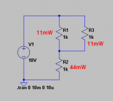
Also try the simple example as per the attached diagrams:
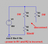
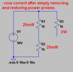
Take for example the simple circuit I have attached pictures for. I have conducted 2 tests as before. In this case when the lower leg of R3 is disconnected and the sim re-run, both R1 and R2 power dissipations come out incorrect! (Test1 = all_connected.png, Test2 = R3 disconnected.png, and after the restoration of probes = R3 disconnected_restored.png.)
Then simply by removing all 3 power probes, and replacing them (nothing else done), the power dissipation in all 3 resistors displays correctly.
1) Make the wire connection to the collector so that the diode and LED are across the L1 inductor.
2) Run the sim
3) Place a power probe on Q1.
4) Do a ctl-right-click to get the average power in Q1, and note the value.
5) Break the connection on the anode side of D1 so that it is no longer connected to the collector of Q1.
6) Re-run the sim.
7) Do a ctl-right-click to get the average power in Q1, and note the value.
8) Delete the trace in the wave form window.
9) Place a power probe on Q1 again.
10) Do a ctl-right-click to get the average power in Q1, and note the value.
At this point you should see that the average power for Q1 changed to the correct value.
Test1: With the connection made to the collector, the correct average power in each is:
PRL = 109.93mW
PQ1 = 16.44mW
Test2: With the connection removed (as shown) to the collector, the correct average power in each is:
PRL = 105.26mW
PQ1 = 385.23mW
The problem occurs if after the Test1 measurement you remove the connection then re-run the sim and re-examine the average powers, the outcome will be as follows:
PRL = 105.26mW
PQ1 = 15.93mW (this is in error as it should be 385.23mW)
In order to get the correct average power for Q1, you have to first remove the power probes, then re-apply them again. Once done, then the average PQ1 power reads correctly.
Also try the simple example as per the attached diagrams:
Take for example the simple circuit I have attached pictures for. I have conducted 2 tests as before. In this case when the lower leg of R3 is disconnected and the sim re-run, both R1 and R2 power dissipations come out incorrect! (Test1 = all_connected.png, Test2 = R3 disconnected.png, and after the restoration of probes = R3 disconnected_restored.png.)
Then simply by removing all 3 power probes, and replacing them (nothing else done), the power dissipation in all 3 resistors displays correctly.
Attachments
Last edited:
Thanks to the help of keantoken my circuit is simulating well enough now, and I do not need to pursue the intricacies of ltspice anymore at this stage.
It is quite often not worth the effort to fix things such as poynt99 mentioned, and you just have to put up with them, for consumer orientated software it is a different matter.
rcw
It is quite often not worth the effort to fix things such as poynt99 mentioned, and you just have to put up with them, for consumer orientated software it is a different matter.
rcw
- Status
- This old topic is closed. If you want to reopen this topic, contact a moderator using the "Report Post" button.
- Home
- Design & Build
- Software Tools
- Things you should know about LTSpice