I'm searching for a S.P.I.C.E model for the lovoltech LD1014 (even if any of the Lovoltech JFET will do just fine).
I saw a previous post but the guy received uncorrelated answers.
What's all this secret about those models?
I've come out with one that fits IV curves nicely, but there's some work to do on the transient response.
Please, if you have any infos, I 'd really like to have a look to it.
I saw a previous post but the guy received uncorrelated answers.
What's all this secret about those models?
I've come out with one that fits IV curves nicely, but there's some work to do on the transient response.
Please, if you have any infos, I 'd really like to have a look to it.
Good
Are you using LTC?
Why did you indipendently modelled those gate, drain, capacitances with external capacitors?
There are two drawbacks to this approch, but I may be wrong.
First, they are partly voltage controlled capacitors. You can include then in the model, and SPICE will take care of those himself.
Second I believe we both made the same error: LTC (if you are using it of course)uses in the fet model zero-voltage Capatacitance values , while those in the Lovoltech datasheet are not.
I have to see better this.
Here there's my model. I suppose beta and lambda are less accurate than yours. Capacitances again, may be wrong as they are not zero-voltage capacitances.
.MODEL LU1014D NJF (VTO=-1.8 BETA=29000M LAMBDA=0.18 RD=0.0065 CGD=363P CGS=784P VTOTC=-2.6M)
Thanks
Giusedia,
Yes I am using LTspice.
It seems the value of lambda I used is high.
I simulate a fet curve tracer with LTspice and try to
fit the model to the curves in figure 8 of the LU1014D
data sheet. I try different values of vto, lamda and beta
to get the curves, then I try the fet model in zen v8 circuit and see
what the currents and gain are. I am really just guessing and tweaking
the fet values. Here is some new fet parameters that might work.
(Vto=-1.8, beta=2 lambda=.7) and change R5 to 22k
The junction capacitances were read off the data sheet. The values are
the 10V vds (-5v vgs) values. Yes you are correct the large signal
fet model does change the cap values with voltage. I put them in there
since the fet is used as a cascode and the junction
voltage changes seem small. Also the default spice
capacitances are zero. I looked up the Shichman and Hodges
model on the web and putting the caps in the circuit seemed ok
to me. I could be wrong.
I think the fet spice models are inadequite to model the power fets.
For example in figure 8 of the data sheet, the vgs=-1v curve has
some curvature to it. I don't think the fet model in the pinch off
region can show curvature(or is it the linear region?).
Using lambda fakes it, since it is similar to an Early voltage.
I am looking through some books I have to find a more basic device
model for fets. It might yield better Id vs Vds (Vgs constant) curves.
Tom
I agree with you, and I also feel the models are inadeguate to model that strange upwards curve we need.
I see that Lovoltech provides S.P.I.C.E models, so we are to wonder if:
-They fake that upwards curve in the way/in a similar way you are doing.
-They provide a macrocircuit that has that curve, thus bypassing the need for a suitable fet model.
-They just don't care, as their product is intended for switching applications and they don't care a lot about the shape of the IV characteristics.
About the capacitances, I also believe the changes would be little, I didn't think we were cascoding.
Why don't you put a current source instead of the resistor?
It surely helped me with supply requirements, but wreaked havoc with the noise.
I can't wait to get a grip on the real jfet and make some real mesurements.
Hi, I've tried to model the LU1014D power JFET for a couple of evenings now and I haven't come up with something useful. So I did a search on google and found this:
http://mixedsignal.eleg.uark.edu/sic/documents/papers/2004/COMPEL_JFET.pdf
Reading the abstract made me glad but as always, the more you read.....
To use the model described in the paper above I need a lot of information from Lovoltech since the input parameters for the model is on process level. And even if I get the parameters I'm not sure that it would be possible to use the model in a Spice simulator.
So, if anyone in this forum have a lot of experience in modelling, please take a look at the paper and tell me if it could be useful.
Does it exist a working Spice model for the LU1014D power JFET that I could get hold off?
Copied from Lovoltech application note:
"Spice models and high level circuit simulation models can be provided to customers for circuit and system simulation"
/Andy
Hi,
using an existing standard JFET model does not work because all this models are based on a quadratic equation in the form:
Id = Ids(1-Ugs/Up)^2
with such an equation it is not possible to model the exponential triode like curve we want to have.
Finding a model should go the following way:
- take a LU1014 and measure it (Lovoltech data is not good enough)
- find a general 3d equation like
Ids=a + b*Vds +c*Vgs + d*Vds*Vgs + e*Vds^2 ....
or something else
- put this in MATLAB and make an variation of the constants a,b...
- put the result in SPICE and thats it
a nice site for this is (for tubes):
http://www.normankoren.com/Audio/
BTW: I wanted to do this, but I have no LU1014
Hi,
kekso22: your idea is good but I have the same problem as you, nothing to measure on. The proposal in the article is to go with the equation below, describing the drain current:
Ijfet= io·[1+tanh{P1(Vgs-Vp)}] ·tanh(áVds) ·e ^ëVds
Tom2: the mesfet model you are using is this something already implemented in LTC or is this your own "tweaked" model?
/Andy
I've been thinking about this, and I believe that our best bet is to run those datasheets into a parameter model extractor such as MODPEX or similar.
That would give us probably an usable model with no hassle.
Actually I'm not sure It would model properly the region of interest.
Unfortunately I was no able to find such a program, and especially nor a free one, even if I recall that Spice-Opus has some limited parameter extraction capabilities.
Anyone with similar programs around?
Myself I'm going to try something with something I have handy.
Bye
Hi,
I just found an interesting program which could help us!
TABLECURVE 3D") @
@
http://www.systat.com/
It is free (30 days trial), has a lot of predefined equations and we can define our own ones.
Bye
I just found an interesting program which could help us!
TABLECURVE 3D
@http://www.systat.com/
It is free (30 days trial), has a lot of predefined equations and we can define our own ones.
Bye
Hi,
a very good description of all the MESFET models can be found in:
http://www.ct.tkk.fi/publications/dt-antti/thesis.pdf
_____________________
let's work now
a very good description of all the MESFET models can be found in:
http://www.ct.tkk.fi/publications/dt-antti/thesis.pdf
_____________________
let's work now
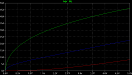
My first results:
I took some values from the LU1014 datasheet and placed this in Tablecurve3D with the model from "Materka-Kacprzak". From the result I made my first LTC-Spice model:
.SUBCKT LU1014 1 2 3 ; D G S
+ PARAMS: a=21.7924 b=4.5599 c=10.2887 d=9.1318 e=61.579
+ f=0.5726 g=-16.0443 h=71.8659
G1 1 3 Value={(a+b*V(1,3))*(1-V(2,3)/
+ (c+d*V(1,3)))**(g+h*V(2,3))*TANH((e*V(1,3))/
+ (a*(1-f*V(2,3))))}
.ENDS LU1014
Ids curves are from Vgs 0v to -2V
Attachments
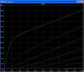
builderandy said:
Tom2: the mesfet model you are using is this something already implemented in LTC or is this your own "tweaked" model?
It's a simplified model I made for LTspice.
The model is far from perfect.
It does not contain any capacitances, but they could be added. I usually
change the diodes to power diodes that LTspice has.
The model can have convergence problems when using it. I added the
uramp functions, that helps a little.
I find checking the noopiter box under the default dc solve strategy
under the spice control panel helps convergence but not always.
I spent alot of time playing with the parameters to get the curves.
I can post the .asc and .asy files I created if you are interested.
I just Googled and found the different models online.
I tried some of simple models and found they did not show the triode region.
I found the TOM3 model and it seemed to work.
I also saw the mathematical methods and tools on the web to derive the equations.
I found the Agilent web site and the spice manual of their product to be very useful.
I'll post a link to it.
The main insight I got running this model was the "triodeness" of
these devices. Plate resistance for example, really
plays into the gain of certain circuits. I've received devices
from Grey and have started playing around with them in the 5mA range
just to build simple circuits and measured results show the triode
character is very evident.
Hopefully soon I will get some simple circuits into a audio system
and hear what these devices really sound like. Also I want to hear
how much 1/f noise they have.
Tom
Attachments

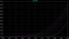
Hi Tom2, copied the model and parameters you attached. The Id_vs_Vds curves are approximately the same as yours and the datablade for LU1014D, but when I simulate Id_vs_Vgs the drain current isn't zero until the "Gate threshold voltage" is reached, see attached picture. Do you see the same in your simulations.
Nice work kekso22, could you comment on the above observations, how is your model working?
/Andy
Nice work kekso22, could you comment on the above observations, how is your model working?
/Andy
Attachments
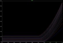
builderrandy said:
Do you see the same in your simulations.
This output is
Id vs Vgs with constant Vds.
Vds = 2,4,6,8,10 volts from right to left.
Tom
Attachments
Here are the working .asc and .asy files I made and use.
I have made the diodes MUR460's. LTspice has the models.
Put the tom3fet2.asc and tom3fet2.asy file in the
same working directory as the .asc schematic files using
the tom3fet2 model.
I have included a Vgs_Id.asc file and
a curve trace file curvetrace.asc file.
Fet parameters can be changed on the tom3fet2.asc file
or on the working .asc schematic file.
Remember my previous post on convergence
problems that can happen using my model.
Have fun.
Tom
Attachments
Hi Andy,builderandy said:Nice work kekso22, could you comment on the above observations, how is your model working?
The "Materka-Kacprzak" or the "TOM3" models are working both. It strongly depends on the constants you choose.
In the meantime I also tried the TOM3 and I find it a little better. The Fitting is more precise.
Emil
Hi Tom,
nice work!
I have put the "TOM3" equations in TABLECURVE3D with some datapoints from the datasheet. The fitting goes very well with this model (better than with the "Materka-Kacprzak" model) and I changed your constants in the asc file. I also included capacitors, which I took from the datasheet @ Vds=2.5V and a gate resistor to stabilize some simulation.
I find, that the uramp is not necessary for every equation (if the constants are correct!). Only for Vds<0 then Ids should be zero.
Don't understand me wrong, yours and mine is not a model we can use, it should only show, that it can be done in such a way.
I'm waiting for real data, but I have no LU1014.
Maybe anybody owning a LU1014 can send us real measured data.
Bye
Emil
PS: example with "TOM3" follows:
Attachments
- Status
- This old topic is closed. If you want to reopen this topic, contact a moderator using the "Report Post" button.
- Home
- Amplifiers
- Pass Labs
- LD1014 SPiCE models