swing the cathode and maybe G1 with a PNP or somesuch.
I went down this road maybe 10 years ago by standing a P channel mosfet follower on its head in the cathode circuit of a conventional pentode while grounding the grid. It seemed to work, but I lost interest for some reason, maybe blown mosfets.
The thought was boosting the efficiency due to the "power pass through" seen in grounded grid RF amplifiers. If you are applying 50 volts of signal swing to the cathode as drive, that 50 volts is added to the total output swing seen by the OPT.
Driving the cathode is interesting in that it also modulates the plate voltage supply some
You still need to raise the total B+ by the amount lost in the silicon, just as you would in a cathode biased amp, so the total dissipation should be about the same. The losses in the tube go down at idle, but idle current in a screen driven tube are pretty low. It may be worth a look someday.
For now I seem to have a handle on the big drive voltage requirements, so I plan to test the usual screen drive stuff with some local feedback, and re-investigate the stuff I did in the old G1=G2 thread. I had an amp running for a few days before I had to stop working on tube stuff for a while.
On PNP/Pchan driving the cathode with the screen V fixed.
Should we call it cathode/screen drive or grounded screen grid mode?
Anyway, besides the extra drive feed through power available in theory, this could be helpful in avoiding excessive screen current at max output power by increasing the plate V at peak power, so keeping it above the screen V. (assuming here that max output is still kept at the original tube capable max, not the driver enhanced max.)
If the cathode drive/fixed screen V can be combined with 50% effective g1 drive (1/Mu drive), then the screen current could be lowered enough (only half the peak screen V needed now) to take advantage of the full driver feed-thru enhanced power capability.
Some while back I tested some HO tubes on the curve tracer, using just a resistive divider from the screen to cathode, to drive the g1 proportionately (1/Mu of the screen drive). Non-linear g1 current (+V on g1, upsetting the R divider) caused some sag in the plate curves toward the knees however. I think I will re-test this with the cathode drive approach, because that would increase the effective plate V at that end, which should prevent some of the sag effect.
One could also just put an N type follower off the R- screen/cath divider to drive g1 effectively, if no sag is tolerable.
Some while back I tested some HO tubes on the curve tracer, using just a resistive divider from the screen to cathode, to drive the g1 proportionately (1/Mu of the screen drive).
6HJ5's if I remember right. I got plenty of them to play with. I am currently wiring up one channel of the monster for drive directly to G2, resistor divider to G1, with a mosfet to feed it all. The first test will be using 6CB5's since the turret board has octal sockets in it and I am too lazy to swap them out.
If you wire the socket like this:
H to pins 2 and 7,
K-G3 to pin 3,
G1 to pin 5,
G2 to pin 8,
and the plate to the top cap, then all of these tubes are pin compatible:
6CB5, 6CL5, 6BG6, 6CD6, 6DN6, 6EX6, 6GC6, 6DQ5, 8236, and 8068.
Power up tonight??????
I think I'm going to use the Hammond transformers after all. I'd feel a lot better cooking a hammond than a Sowter or Lundahl.
So, I'm going to try these tubes in PPP with 350V b+ into 1.9K in pentode mode.
If that doesn't do it, I will use a doubler for my 680-700V B+ to the plates.
I'd love to see your tests George along with schematics for your drive rig.
So, I'm going to try these tubes in PPP with 350V b+ into 1.9K in pentode mode.
If that doesn't do it, I will use a doubler for my 680-700V B+ to the plates.
I'd love to see your tests George along with schematics for your drive rig.
!!!! DUAL DRIVE IS ALIVE !!!!
After blasting the screens out of a pair of 6BQ6GT's nearly 5 years ago I believed that driving only the screen grids in a demanding application would blow them up. Experiments proved this to be true.
A few years ago I made a little test amp that showed driving G1 and G2 simultaneously might cure this failure mechanism. After several years of dreaming and drawing paper amps, I have finally seen the light......uh absence of light...That's right MIND BLOWING POWER flowing with nothing glowing????? Could this be right, Kaptain Kilowatt is hungry, hasn't been fed in years and nothing gets blown up. Well, I did melt the solder on a resistor a few nights ago. SO, here's the deal.
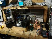
I wired my driver board up to a pair of 6CB5's. I put all the good OPT's far away from this thing, and connected up a sacrificial test transformer that I got for $16. I connected the 16 ohm secondary to a Dale Precision 1% 8 ohm resistor......
I turned up the drive until clipping just appeared. Distortion was 4%.Power Output was 180 watts The amp ran at this level for several minutes. Then I turned the audio generator up 10 db beyond clipping. No smoke, no glowing grids, just 299.9 watts.
After blasting the screens out of a pair of 6BQ6GT's nearly 5 years ago I believed that driving only the screen grids in a demanding application would blow them up. Experiments proved this to be true.
A few years ago I made a little test amp that showed driving G1 and G2 simultaneously might cure this failure mechanism. After several years of dreaming and drawing paper amps, I have finally seen the light......uh absence of light...That's right MIND BLOWING POWER flowing with nothing glowing????? Could this be right, Kaptain Kilowatt is hungry, hasn't been fed in years and nothing gets blown up. Well, I did melt the solder on a resistor a few nights ago. SO, here's the deal.
I wired my driver board up to a pair of 6CB5's. I put all the good OPT's far away from this thing, and connected up a sacrificial test transformer that I got for $16. I connected the 16 ohm secondary to a Dale Precision 1% 8 ohm resistor......
I turned up the drive until clipping just appeared. Distortion was 4%.Power Output was 180 watts The amp ran at this level for several minutes. Then I turned the audio generator up 10 db beyond clipping. No smoke, no glowing grids, just 299.9 watts.
Attachments
{"I think I'm going to use the Hammond transformers after all. I'd feel a lot better cooking a hammond than a Sowter or Lundahl."} deicide67
I just finished an amp using the Hammond 1.9K P-P 120Watt with DA42's real zero bias triodes at 580 volts. Used 6BL7's cathode followers, instead of Mosfets . 70 mills current draw on the DA42's. no signal.
I have made several using Sowter, but the Hammond sound excellent and a fraction of the cost. the Sowter costs over $1000 to get to Australia. Going to try the Big Hammond 280 [$350] watt transformers, when i get the heavy weight 4 mill boxes from the metal works.
Phil
Can feel the power flowing, lights browning out on the East coast here. 299.9 Watts from 26 watter tubes, impressive. That load resistor looks like a 100 watter, better get a fan.
What division of grid drive voltages are you using for this, 3.8? (ie, Mu) Would be interesting to measure the grid2 current at the max power levels and the peak g2 volts, and the minimum plate to cathode volts at max current. Is g1 setting at zero volts bias, or something negative?
What division of grid drive voltages are you using for this, 3.8? (ie, Mu) Would be interesting to measure the grid2 current at the max power levels and the peak g2 volts, and the minimum plate to cathode volts at max current. Is g1 setting at zero volts bias, or something negative?
Last edited:
{"I think I'm going to use the Hammond transformers after all. I'd feel a lot better cooking a hammond than a Sowter or Lundahl."} deicide67
I just finished an amp using the Hammond 1.9K P-P 120Watt with DA42's real zero bias triodes at 580 volts. Used 6BL7's cathode followers, instead of Mosfets . 70 mills current draw on the DA42's. no signal.
I have made several using Sowter, but the Hammond sound excellent and a fraction of the cost. the Sowter costs over $1000 to get to Australia. Going to try the Big Hammond 280 [$350] watt transformers, when i get the heavy weight 4 mill boxes from the metal works.
Phil
No doubt that Hammond isn't shabby. I've used the 1650W 280W outputs before. Big iron!! I have at my home now, lundahl LL1679 (188W 2.6K), hammond 1650T (1.9K at 120W, and Sowter 200W (1.5K) transformer.
The Sowters and Lundahls are expensive. At least, to me they are. The Hammonds were inexpensive through a friend.
I'm still scared to death to try the screen drive stuff. It is way over my head. Do you have a schematic of your zero bias circuit multi?
Can feel the power flowing, lights browning out on the East coast here. 299.9 Watts from 26 watter tubes, impressive. That load resistor looks like a 100 watter, better get a fan.
indeed....

@decide, the screen grid drive circuit is also called a zero bias circuit
due to the very low plate current of about 3mA at idle, compare that
to kt88 amps that idle at around 60mA each plate..
otoh, multi's triodes have 0 volt grid bias....
...
If you wire the socket like this:
H to pins 2 and 7,
K-G3 to pin 3,
G1 to pin 5,
G2 to pin 8,
and the plate to the top cap, then all of these tubes are pin compatible:
6CB5, 6CL5, 6BG6, 6CD6, 6DN6, 6EX6, 6GC6, 6DQ5, 8236, and 8068.
...
And 7867 also...
I flipped the big switch late last night, and I don't like playing with this much electricity late at night when I'm the only one home, so I didn't get all the measurements done, but:
Yes, my experiments that could end badly always use these 6600 ohm OPT's. They work pretty good as 3300 ohm OPT's too, which was the case here. I got 200 of them about 15 years ago to make guitar amps. In that time I have set one on fire. The load resistor blew open during a high power test.
I think it is 125 watt. It was too hot to touch. I have a 500 watt resistor, which will be installed. I never thought this thing would work on first power up. I was expecting blown parts!
The voltage division was 5:1, based entirely on the biggest resistors I could
find at build time. 10K 6.5 watt (the black ones) and 2500 ohm 5 watt (blue).
It was late last night and I neglected to write down some important numbers. Sadly I won't have much time to play with this for about 2 weeks. Some important stuff that I did write down:
For initial power up I set the bias to well below cutoff (both grids negative). There is one pot for each output tube that moves both grids together. I turned it up until there was 5 mA per tube and applied signal. Crossover distortion was visible at low power. I applied enough signal to get 1 watt output and tweaked all the pots on the board to get minimum distortion. It was about 0.5% at an idle current of 15 mA per tube. Distortion at 180 watts was 4.79%.
The schematic of the driver board is here. It uses 3 power supplies not counting the 6.3 Vac. As it is now, each is connected to a variable bench supply. The connector in the upper right on the schematic is B+/-. Pin 1 is connected to a negative voltage source, currently set to -80 volts. Pin2 is ground, Pin 3 is the B+ supply to the drivers and screen mosfets. It is set to +350 volts. Just to the left of it is the B++ connector, it goes to Kaptain Kilowatt which is set on 600 volts.
The output stage is not shown but is real simple. Pin 1 of each OUT connector goes directly to the screen grid of the output tubes. A 10 K resistor goes from G2 to G1 and a 2.5K resistor goes from G1 to the B- supply (currently -80 volts). There is a 10 ohm resistor fron the cathode to ground, and an OPT from each plate to B++. The OPT measures 50 ohms DCR in one side, and 60 ohms in the other.
This itteration idles with G1 at -30 volts and G2 at 150 volts. At 180 watts output G1 swings from -60 volts to 0 volts and G2 swings from 0 volts to +300 volts.
The idle current for the +350 volt supply is about 80 mA. About 50 mA of this is also flowing through the -80 volt supply. When the amp is cranked to 300 watts of square wave output, the 350 volt supply reads about 140 mA. I didn't check the negative supply. Some of this is eaten by the driver tubes, but I'm guessing a lot of it still goes into the screen grids.
The B++ supply feeds the driver plates and the output tube plates. Its meters read 600 volts and around 450 mA at 180 watts output. The drivers eat about 20 mA each.
There is a voltmeter across the 10 ohm resistor in each cathode. They just over range (LCD goes blank) on the 2 volt scale at 180 watts. This looks like about 400 mA of combined tube current at about 590 volts. This looks like about 76% efficiency. It's probably a little better since screen current is being measured too.
No attempt was made to optimze anything, or even turn any knobs. Clearly there is more to be done, but it is a good start so far.
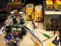
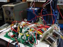
Hey, this is one of my better looking prototypes. It's going to wind up in the trash when the real amp gets built, so.....
I added a picture of another one of my prototypes. Yes there is a working HiFi amp built with clip leads and a dead SSE board.
What is the plate load? 3.3K as you said?
Yes, my experiments that could end badly always use these 6600 ohm OPT's. They work pretty good as 3300 ohm OPT's too, which was the case here. I got 200 of them about 15 years ago to make guitar amps. In that time I have set one on fire. The load resistor blew open during a high power test.
That load resistor looks like a 100 watter, better get a fan.
I think it is 125 watt. It was too hot to touch. I have a 500 watt resistor, which will be installed. I never thought this thing would work on first power up. I was expecting blown parts!
What division of grid drive voltages are you using for this, 3.8? (ie, Mu)
The voltage division was 5:1, based entirely on the biggest resistors I could
find at build time. 10K 6.5 watt (the black ones) and 2500 ohm 5 watt (blue).
Would be interesting to measure the grid2 current at the max power levels and the peak g2 volts, and the minimum plate to cathode volts at max current. Is g1 setting at zero volts bias, or something negative?
It was late last night and I neglected to write down some important numbers. Sadly I won't have much time to play with this for about 2 weeks. Some important stuff that I did write down:
For initial power up I set the bias to well below cutoff (both grids negative). There is one pot for each output tube that moves both grids together. I turned it up until there was 5 mA per tube and applied signal. Crossover distortion was visible at low power. I applied enough signal to get 1 watt output and tweaked all the pots on the board to get minimum distortion. It was about 0.5% at an idle current of 15 mA per tube. Distortion at 180 watts was 4.79%.
The schematic of the driver board is here. It uses 3 power supplies not counting the 6.3 Vac. As it is now, each is connected to a variable bench supply. The connector in the upper right on the schematic is B+/-. Pin 1 is connected to a negative voltage source, currently set to -80 volts. Pin2 is ground, Pin 3 is the B+ supply to the drivers and screen mosfets. It is set to +350 volts. Just to the left of it is the B++ connector, it goes to Kaptain Kilowatt which is set on 600 volts.
The output stage is not shown but is real simple. Pin 1 of each OUT connector goes directly to the screen grid of the output tubes. A 10 K resistor goes from G2 to G1 and a 2.5K resistor goes from G1 to the B- supply (currently -80 volts). There is a 10 ohm resistor fron the cathode to ground, and an OPT from each plate to B++. The OPT measures 50 ohms DCR in one side, and 60 ohms in the other.
This itteration idles with G1 at -30 volts and G2 at 150 volts. At 180 watts output G1 swings from -60 volts to 0 volts and G2 swings from 0 volts to +300 volts.
The idle current for the +350 volt supply is about 80 mA. About 50 mA of this is also flowing through the -80 volt supply. When the amp is cranked to 300 watts of square wave output, the 350 volt supply reads about 140 mA. I didn't check the negative supply. Some of this is eaten by the driver tubes, but I'm guessing a lot of it still goes into the screen grids.
The B++ supply feeds the driver plates and the output tube plates. Its meters read 600 volts and around 450 mA at 180 watts output. The drivers eat about 20 mA each.
There is a voltmeter across the 10 ohm resistor in each cathode. They just over range (LCD goes blank) on the 2 volt scale at 180 watts. This looks like about 400 mA of combined tube current at about 590 volts. This looks like about 76% efficiency. It's probably a little better since screen current is being measured too.
No attempt was made to optimze anything, or even turn any knobs. Clearly there is more to be done, but it is a good start so far.
My test apparatus will look a bit prettier,
Hey, this is one of my better looking prototypes. It's going to wind up in the trash when the real amp gets built, so.....
I added a picture of another one of my prototypes. Yes there is a working HiFi amp built with clip leads and a dead SSE board.
Attachments
I was expecting blown parts!
So are we!
And that is why we are cheering you on (from a safe distance)

I'm getting some good ideas here on what to use the big PTs that are on my shelf for many years now. 450 Vac, 6,3V @ lotsaamps... I'm developing a need for some serious output iron...
what is it with this hobby that makes one dream of bigger, heavier and less and less usefull power levels?
!!!! DUAL DRIVE IS ALIVE !!!!
I turned up the drive until clipping just appeared. Distortion was 4%.Power Output was 180 watts The amp ran at this level for several minutes. Then I turned the audio generator up 10 db beyond clipping. No smoke, no glowing grids, just 299.9 watts.
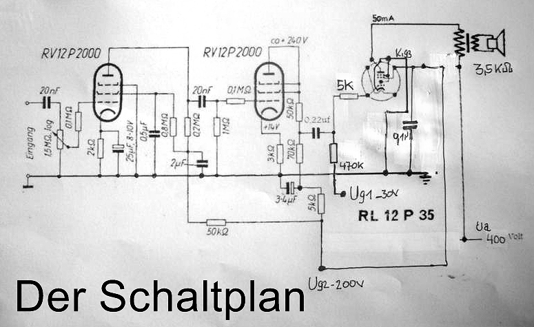
You've got me thinking - your circuit may be what the doctor prescribed for these 12RLP35 WWII German pentodes:
An externally hosted image should be here but it was not working when we last tested it.
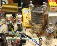
Holy frankentube!!
Frankentube is the big one in the background, the mighty 833A. That's a 12AU7 in the front. It was originally designed for AM broadcast transmitters. I put together a little prototype guitar amp using one in SE. Check out the hose clamp and vise grip tube socket! It cranked out 200 very loud watts from 1500 volts, which flows through the yellow Radio Shack clip lead! This amp existed for about 10 days 6 years ago. It survived my guitar playing for several hours only blowing the 15 amp bench breaker twice. I still have a few tubes and an OPT and PT for that guitar amp, but would I ever use it?????
Tony has been waiting patiently for a long time for me to test the "little tube" in the foreground. I will get to them.....
Some 13GB5's need to DIE ! ........I was expecting blown parts!.....So are we!....And that is why we are cheering you on (from a safe distance)
OK, I see what everybody wants.....I blow stuff up so you don't have to!!!!! I can accept this challenge. I have 150 or so 13GB5's. Most are good quality Mullards, but I do have about 15 or so cheap looking "Made in Korea" tubes.....I will explore their melting point.
So far every time I play with screen drive, something gets blown up. Usually its tubes or mosfets, or both. Maybe I need to get the video cam for some YouTube action???? Motorola gave me a Sony Handy Cam for my 40th service anniversary and I have never used it.
I powered the amp up and tried turning knobs on the power supplies. Increasing the negative voltage supply lowers the voltage on G1 in the 6CB5's this allows more drive before grid current happens, which allows more power, but causes G2 to be driven higher......which causes the dreaded screen grid glow of death. Glow comes on quickly and BRIGHT. This is how I blew up a 6BQ6GT, so I was being very cautious. The edge is 215 watts, at which point the distortion is about 4%, but glow appears rather quickly at 220 watts. During the experiment I smelled something burning so I killed power. It turned out to be the load resistor. The OPT was hot from conducted heat. Time to get the big resistor. I tried other combinations of power supply voltages, but haven't yet ventured beyond 600 volts of B++, but 215 watts seems to be the limit.
So it's still possible to melt a screen grid, but come on, 200+ watts from a pair of $2 tubes.....Maybe I will just set the B+ to a safe value of 275 to 300 volts and call it a 150 watt amp. The big Edcors going into the final amp are only rated for 100 watts. Kaptain Kilowatt goes to 650 volts, so maybe I need to turn that knob????
Attachments
Maybe I need to get the video cam for some YouTube action???? Motorola gave me a Sony Handy Cam for my 40th service anniversary and I have never used it.
Yes, we definitely need to see some "live" action, with narration
jeff
- Home
- Amplifiers
- Tubes / Valves
- Show me your screen drive circuits