Nice design, using Hawksford's error correction around the output stage. Some months ago, I thought there were not many amplifiers using this technique, but it seems they are just good sounding secrets  .
.
For those who are interested in other designs using this technique (both with and without overall feedback):
http://www.diyaudio.com/forums/showthread.php?postid=330446#post330446
http://www.diyaudio.com/forums/showthread.php?postid=330997#post330997
http://wes.feec.vutbr.cz/~gratz/Download/Hawksford.ZIP
http://wes.feec.vutbr.cz/~gratz/Download/Cordell.ZIP
Steven
.For those who are interested in other designs using this technique (both with and without overall feedback):
http://www.diyaudio.com/forums/showthread.php?postid=330446#post330446
http://www.diyaudio.com/forums/showthread.php?postid=330997#post330997
http://wes.feec.vutbr.cz/~gratz/Download/Hawksford.ZIP
http://wes.feec.vutbr.cz/~gratz/Download/Cordell.ZIP
Steven
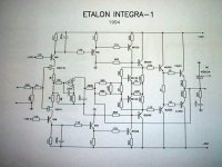
I'm a bit surprised though by the triac at the output of the Etalon amplifier. This must be to short circuit the output in case of DC on the output if anything goes wrong with the amplifier. Quad uses the same approach to avoid relay contacts in the output.
But the Quad amplifier uses current limiters in the output stage, while the Etalon amplifier has not. I hope the power supply is current limited... or else a DC-error might blow the output stage.
Steven
But the Quad amplifier uses current limiters in the output stage, while the Etalon amplifier has not. I hope the power supply is current limited... or else a DC-error might blow the output stage.
Steven
The one on the left across the bases of the combined Vbe multiplier/error correction amplifier is for bias current adjustment.
The one on the right connected to the emitters of the Vbe multiplier/error correction amplifier is to adjust exact error cancellation. In that case the output impedance of the amplifier will be zero! Adjustment is easy: just connect a load resistor to the amplifier intermittently and look at the ouput voltage (sine wave) of the amplifier. Normally the output voltage will slightly decrease when loaded, but now adjust the preset such that the voltage will not drop. If you continue to change the preset, then the voltage will even increase when loaded (negative output resistance). The beauty of this preset arrangement is that the bias current and the error correction adjustment is independent of each other: it is (almost) free of interaction. Furthermore both adjustments operate for both halves of the output stage simultaneously, i.e. the positive half and the negative half.
Steven
Charles,
Wow! You are right. I much like the buffer between the first two stages. Aragon used in their amps. I wonder if replacing the 1k resistor with a current source would help? ( Rhetorical question...... )
Regards,
Jam
P.S. The servo has got to go......................
Wow! You are right. I much like the buffer between the first two stages. Aragon used in their amps. I wonder if replacing the 1k resistor with a current source would help? ( Rhetorical question......
)Regards,
Jam
P.S. The servo has got to go......................
jam said:I wonder if replacing the 1k resistor with a current source would help?
P.S. The servo has got to go......................
Replacing the resistor with a current source would be a tradeoff. You would have much better rejection of the noise on the PS rails, but you will also find that it is very difficult to maintain DC balance without the servo....
If you want to get rid of the servo, I would also suggest getting rid of the error correction. In my experience you are better off just adding another pair (or two or three) of output devices. This is particularly true for this design as the triple emitter-follower output stage will be able to drive low impedance loads quite well.
I'm not sure why the original schematic has the slow-down capacitors in the first stage. Normally you would see this kind of "trick" employed when trying to stabilize a circuit with global feedback. Since this design has no global feedback, these capacitors won't help with any stability issues.
Hi,
I knew you'd have to come with that, Jam...
The more I look at the circuit, the more I like it...yummie.
While I haven't heard from Etalon in ages, I can only say that in those days they were considered a revelation as far as solid state amps went.
Anyone lnow what the triac is? BT139 perhaps?
Cheers,
I wonder if replacing the 1k resistor with a current source would help? ( Rhetorical question...... )
I knew you'd have to come with that, Jam...
The more I look at the circuit, the more I like it...yummie.
While I haven't heard from Etalon in ages, I can only say that in those days they were considered a revelation as far as solid state amps went.
Anyone lnow what the triac is? BT139 perhaps?
Cheers,
Hi, Steven,
Thanks for your explenation. I also look at the url you pointed. I just dont understand this 0 impedance thing. I never learn it in the handbook. Could you give a little explenation how it works? Voltage trace, current trace, or anything to make me understand this. Is it true can lead to infinite damping factor? How does it sounds?
Is this only applicable to non-feedback type of amp? Or it can be applied to ordinary feedback/3stages amp?
Charles,
I would have to agree with you on the most part but I am trying to understand what the tradeoff would be if you did the other things you proposed.
Do you agree with the values of emitter resistors used in the triple.
Frank,
Now if we can find a place to insert 6.3v somewhere.............
I would have to agree with you on the most part but I am trying to understand what the tradeoff would be if you did the other things you proposed.
Do you agree with the values of emitter resistors used in the triple.
Frank,
Now if we can find a place to insert 6.3v somewhere.............
lumanauw said:Hi, Steven,
Thanks for your explenation. I also look at the url you pointed. I just dont understand this 0 impedance thing. I never learn it in the handbook. Could you give a little explenation how it works? Voltage trace, current trace, or anything to make me understand this. Is it true can lead to infinite damping factor? How does it sounds?
Is this only applicable to non-feedback type of amp? Or it can be applied to ordinary feedback/3stages amp?
Looking at the circuit below:
Q2/Q5 is a normal voltage follower output with a gain slightly less than one. Q3/Q6 together with R3 and R4 (and R5) define the bias current of the output stage. At the same time Q3/Q6 act as an error correction amplifier to make the gain of the output stage exactly one by modulating the voltage drop over R1. Q3/Q6 compare the base voltages of Q2/Q5 (via R2) to the output voltage (divided by R4 and R3). So it also compensates for the voltage drop across R5; therefor R5 should be quite small.
A voltage gain of one is obtained for R2/R1=R3/(R3+R4).
This is the basic circuit. Adding some presets for bias and error adjustment makes the equation a little less transparant.
Lumanauw, yes, the output impedance goes to zero and the damping factor goes to infinity. I think it sounds very good, at least it did when I built one 21 years ago. PMA mentioned here that the circuit of Upupa Epops has gained quite some fame.
This principle can be used both with feedaback amplifiers and non (overall) feedback amplifiers. Upupa Epops and Robert Cordell use feedback. Etalon and I did without.
Steven
Attachments
Hi Lumanauw,
You can calculate these values for yourself, but it takes some wye-delta transformations to make the circuit comparable to my basic circuit. But at first glance it looks like the Etalon circuit does not use presets but just a selected relatively high value resistor in parallel to the 2k and 1k resistor. It looks like the fixed values are already quite good. Just start with a value about 10 times higher than the fixed 2k or 1k resistor and go down. The adjustments are quite orthogonal, but I would start with adjusting the bias.
Steven
Hi, Steven,
In ordinary amp design, the Vbe multiplier is usually attached to heatsink, to get temperature compensation. In this design, BD139-140 are running other function also, as error correction. In this Etalon design, can those transistors be put in heatsink to get temperature compensation effect? Or it shouldn't be on heatsink?
What if the transistors are mosfets and fets (doesn't draw current for base). Does your mechanism of error correction can works also with fets and mosfet outputs?
- Home
- Amplifiers
- Solid State
- ETALON-schematics?