Came across this patent application US2004/0251079 A1 which is also backed up by a functioning company actually building product. This might be a more fruitfull design to look into (as opposed to the Holliman Infrabass). Here is a link to the company's site though you will not find much info there with respect to how or why the design works. They do however have a number of products with measurements. The working principal may be of interest if you can figure it out. I have only skimmed the patent application an it does look to be kind of interesting. I just thought that some here might find it of interest. Regards Moray James.
Patent Application http://aiw2.uspto.gov/.aiw?Docid=20...ageNum=&Rtype=&SectionNum=&idkey=389ED53DA4F0
Company link http://www.tbisound.com/index.asp
Patent Application http://aiw2.uspto.gov/.aiw?Docid=20...ageNum=&Rtype=&SectionNum=&idkey=389ED53DA4F0
Company link http://www.tbisound.com/index.asp
United States Patent Application 20040251079
Kind Code A1
Plummer, Jan Princeton December 16, 2004
--------------------------------------------------------------------------------
CLOSED LOOP EMBEDDED AUDIO TRANSMISSION LINE TECHNOLOGY FOR LOUDSPEAKER ENCLOSURES AND SYSTEMS
Abstract
An acoustic impedance matching enclosure is provided having a driver loaded into a chamber buffering the throat/mouth of a closed loop transmission line. Transmission line consists of a termination member, outer and inner enclosure walls, high-density lining and throat/mouth area. Transmission line eliminates internal random standing waves while providing variable-frequency standing waves that through superposition of the waves compensates for mass-acceleration loss of the high-end of the driver output while damping the resonance of the driver. Alternative application of the acoustic impedance matching enclosure is that of compression loading the driver directly into the closed loop transmission line and using an acoustic low pass filter to translate the output into low frequencies only through a port. Both applications of the acoustic impedance matching enclosure are to insure that the drivers' diaphragm is clear of disruptive internal standing waves, properly loaded at all frequencies and not easily affected by room reflections.
--------------------------------------------------------------------------------
Inventors: Plummer, Jan Princeton; (Marietta, GA)
Correspondence Name and Address: JAN P. PLUMMER
341 ENGLAND PL NE.
MARIETTA
GA
30066
US
Serial No.: 709538
Series Code: 10
Filed: May 12, 2004
U.S. Current Class: 181/199; 181/156
U.S. Class at Publication: 181/199; 181/156
Intern'l Class: A47B 081/06
thanks Dennis...
I forgot about these guys. They would seem to be the easiest way to down load the patent and drawings in one easy proceedure.
So I will assume that you had a look at this idea, do you have any thoughts or comments on it? I appreciate your ability to get to the heart of a design and so clearly explain its workings.
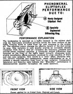
The internal sealed line must increase the radiation resistance that the driver sees over a wide band. This very much reminds me of the Eliptoflex (see attached) method of vent loading similar also to the JR reflex loading principal. I guess that the bends in the line generate turbulence which helps to increase the load of such a small line. How well this idea works is hard to say not having heard one but they exist and are being sold. The 6 moons review was of interest. I also see physical similarities to the S.A.F.E. loading method which had a series of vertically stacked plates with small spacing forming a kind of transmission line.
Any and all comments would be welcome. Regards Moray James.
I forgot about these guys. They would seem to be the easiest way to down load the patent and drawings in one easy proceedure.
So I will assume that you had a look at this idea, do you have any thoughts or comments on it? I appreciate your ability to get to the heart of a design and so clearly explain its workings.
The internal sealed line must increase the radiation resistance that the driver sees over a wide band. This very much reminds me of the Eliptoflex (see attached) method of vent loading similar also to the JR reflex loading principal. I guess that the bends in the line generate turbulence which helps to increase the load of such a small line. How well this idea works is hard to say not having heard one but they exist and are being sold. The 6 moons review was of interest. I also see physical similarities to the S.A.F.E. loading method which had a series of vertically stacked plates with small spacing forming a kind of transmission line.
Any and all comments would be welcome. Regards Moray James.
Attachments
I have both of the patents now and the one main difference is that the sealed "transmission line" is open ended in the older patent and closed at the end in the newer one. There are other differences too, but that is the most significant. The diagram in figure 6 of the newer patent, which is most likely to be the commercial subwoofer only model, (but in this case without the side length extensions) is almost identical to the older patent model; again, the difference being the open ended "tl" terminus on the older one.
The 6moons review is extremely positive, as far as I'm concerned, especially with regard to the subwoofer unit. The one they reviewed is the one designed from the old patent. You can see the open mouth along the edges in the bottom view picture of the unit. Unfortunately, the newer unit was not reviewed because of complications with the inventor's new and old affiliates. This leads me to question whether the new unit is actually an improvement over the older one or if the inventor just needed a new product for his new company. Either way, at least the old one (subwoofer module) got a great review.
Figure 6 could probably be used to copy the new commercial model, unfortunately there are no measurements and there are a lot of unknown factors - the volume of the resonant enclosure, which side of the baffle the driver is mounted on, driver parameters, exact dimensions of the "tl" section, thickness and density of the absorbtion material and the final output port length are all relatively unknown.
From the commercial model we know exterior dimensions, output port diameter (2 inches) and average sensitivity in the range of 87 db/1w/1m. By all indications this box goes incredibly low considering it's size and the driver in it, but not incredibly loud.
Overall, it might be fun to try to make a box based on the new commercial unit's measurements and the diagram in figure 6 of the new patent and then try auditioning drivers. But other than that, there is just not enough information. I would be wary to scale all measurements by cone size difference.
A stereo or quad set of these might do the trick very nicely, (and dirt cheap) possibly as a base for an OB baffle.
just a guy said:A stereo or quad set of these might do the trick very nicely, (and dirt cheap) possibly as a base for an OB baffle.
This is what goes at the bottom of my latest OB baffle, a 15's pushed up behind the holes still to be cut in the baffles pictured. I'd never give up OB bass.
An externally hosted image should be here but it was not working when we last tested it.
Looks like plenty of info...
to get started with. I get the impression that you want the cavity to be acoustically small more of a coupling chamber of sorts. You might want to try making the closed line as long as possible with as many folds as possible and the cavity as small as possible. The patent shows the line is lined with open cell foam but that there is an air gap. This suggests to me the designer may want to induce as much turbulence as possible to increase radiation resistance (hence the 90 degree bends in the line). Since it is the line that is offering the wide band load I would imagine that multiple lines would be benefical. If a number of lines were "nested" about the back side of the driver with just enough space to act as a manifold to the lines that would take care of keeping the cavity volume to a minimum while presenting a number of increasingly longer closed lines to further spread the load.
I am just discussing off the top of my head here so no theory to back this up. To me the cavity is not the real active load here that would appear to be the line. Given the results that can be obtained with a little driver this would seem to be a great diy project. Fostex make some nice tiny woofers that might work well. I would feel a lot safer jumping into knocking up one of these rather than the bulk and expense of a Holliman. Since they are so small and cheap to build. I really thing that ultimate output is not much of an issue just build more if you like what one does. Four or eight of these would be easy to distribute throughout a room. Five such small units could also be built into a small manifold and used to load a room from one point or even used to load a large reflex cabinet. Lots of posibilities to play with. Regards Moray James.
Moray, I think you mean the RJ (not JR) principle See this thread:
http://www.diyaudio.com/forums/showthread.php?threadid=53457
http://www.diyaudio.com/forums/showthread.php?threadid=53457
John - just wondering - do you have a warehouse down there in CR? Cuz that's the fourth pair of new speakers I've seen from you in about a month... I need new mains anyway and I have been considering OB for extra clear vocals but I had been planning to use them only 80 hz and up. Then those nifty $60 Mach 5 MAW18's came out (claimed to be suitable for OB bass) but I'm undecided on those. I'd do it in a heartbeat if I was sure to get down to 20 hz fairly flat - but I hate eq - maybe I'll have to learn to live with it one day. These are an especially good deal for me, because driver selection is not so good here and shipping is too expensive to order from the US in many cases.
But about the design in question - since OB's have been brought up, I was wondering how much advantage there would be to these subwoofers vs. the same driver in a ripole (or a couple on a W baffle). Probably about the same low end extension but the Plummer box would probably be a bit louder while the ripole would probably sound a bit better. Just a guess of course.
Moray - are you contemplating the closed sub only model or one of the ones with the driver cone firing into the room (full range)? Just wondering because this design accomodates both types, and I certainly wouldn't waste a fostex driver on a subwoofer.
I'm still stuck on the Holliman box for the low lows because without major mods this new box only starts to get going where the Holliman box will be quitting (around 25 hz). And like I said before there's already too many variables just trying to copy the commercial version as is.
But if you think you can and you want to try I'll make you a deal. I'll make and document the Holliman box (remember I have no measurement tools) if you do the same with this one.
After reviewing the patent, I think it might be interesting to take a look at the Hegeman Loudspeaker, which used a series of quarter-wave "stubs" (that is, a line with one end capped) to provide resonant loading to a driver. I think I still have an AudioXPress magazine documenting the development of a subwoofer using the principle of the Hegeman loudspeaker cabinet and an Adire Audio Brahma subwoofer driver. The reason I say this is that the embodiment of the transmission line in the ETL designs (Magellan subwoofers, Diamond single-driver monitors) also uses a closed end, making the terminus the same as the throat of the line. However, I think that it's important also to take into account the expansion profile of the initial segment of the transmission of the line (a profile created by the cylindrical expansion of the wave, which must then be forced back through the same small opening according to the superposition principle.
more later.
more later.
Since a quarter-wave stub is closed at one end, and upon reaching the end of the tunnel, the wave is reflected back to the open end, the effective length being double the actual length. Since the tunnel is a quarter-wavelength long, the wave exiting the pipe is 180 degrees out of phase with the wave entering the pipe. (Low acoustic impedance?) But the wave exiting the pipe will provide resonant reinforcement at a lower frequency, where the pipe length is 1/8 of the wavelength of the signal. This should help put the brakes on cone movement. (High acoustic impedance?)
The TBI patent application remarks that in tuning the line, it is the quarter-wavelength frequency of the line that we should be concerned with, and that the objective is a low acoustic impedance at the tuning frequency. I think this is beginning to make sense -- the line exhibits a low acoustic impedance at the 1/4wl frequency, allowing the driver to more effectively work against its own mechanical compliance in that range. This would not add mass to the driver diaphragm, and it would allow the driver to still perform effectively (though excursion-limited) at the quarter-wave frequency of the line, even though that frequency may be substantially lower than Fs. So, that's the direct-coupled embodiment of the embedded transmission line theory -- not much different from what Hegeman did in his loudspeakers, except that they used a decoupling chamber of a certain volume behind the driver's diaphragm. The Diamond satellite speakers also use a similar decoupling chamber.
It seems like the desired net effect of the TBI design, by decreasing the acoustic impedance seen by a side of the driver, is causing the driver to think that it is in an enormous enclosure, instead of in a tiny one. It made sense when I considered the incredibly long port that is in the TBI Diamond satellite speakers. As the enclosure size is decreased, the port needs to be longer, but it also requires more force from the loudspeaker's motor to overcome the very high acoustic impedances.
I'll do some more reading to see what else I can dredge up.
Addendum: As mentioned in the Hegeman Subwoofer article, these guys in Canada build a loudspeaker similar to the original Hegeman, also using quarter wave stubs like in the original. http://www.morrisonaudio.com/morrison_loudspeakers.htm
just looking so far...
Quote "Moray - are you contemplating the closed sub only model or one of the ones with the driver cone firing into the room (full range)? Just wondering because this design accomodates both types, and I certainly wouldn't waste a fostex driver on a subwoofer." end quote.
no plans for this, still reading and thinking. Fostex have small bass drivers so why would you not want to use one? Aside from price they make good designs. Would probably be best to experiment with inexpensive drivers first.
Don't wait for me. Build your Holliman and see what you can do with it. I don't think that I would build a copy of the Plummer design. Rather I think I would build something along the lines of what I discribed earlier. No time to build one of these right now. Would like to listen to additional thoughts from others who find the idea interesting before making any decissions.
Bam: yes I see the similarity with the Hageman and that was similar to what I had in mind when I suggested multiple length lines. I am surprised that Plummer got past that one at the patent office The physical similarities are striking.
I have an idea that the line(s) could be eliminated all together for a simpler concstruction method. Plummer mentions that the turbulence in the corners of the line is important and he makes sure that his lines are not filled with foam but that there is an air gap, so more turbulence (loss). Ok so if you built a box in which you had alternating layers of open air and a rigid porus layers around the driver. You can imagine it as a series of nested porus walled boxes over the back side of the driver with a wall thickness of say 1/2 inch and then an open air space of a 1/2 inch and so on. The porus material could be like a filter material. The first material that comes to mind is the open cell high density foam material that florests use to hold floral arrangements (the wet version rather than the dry). The effect of alternating compression and decompression layers (foam/air) is I think very important and if you wanted to utilize reflex loading you would need to leave open a volume of air large enough to accomodate the reflex action of the air inside the vent. Recall the the air inside a reflex vent will easily travel in and out of the vent 100% of its volume so an available cavity volume of at least that minimum size should be provided and larger would be preferable.
Ther you go that's the idea. Coments? Regards Moray James.
The Hegeman's quarter-wave stub action was employed to smooth impedance peaks, however, so the true goal in their application was improving transient response, where the action of the stub in the TBI design is to decrease acoustic impedance in a very small box at the appropriate operating frequencies.
TBI's quarter-wave stubs are very small, though. I wonder if there is any way to determine how small these stubs can be, other than trial and error.
TBI's quarter-wave stubs are very small, though. I wonder if there is any way to determine how small these stubs can be, other than trial and error.
- Status
- This old topic is closed. If you want to reopen this topic, contact a moderator using the "Report Post" button.
- Home
- Loudspeakers
- Subwoofers
- A little working miracle?