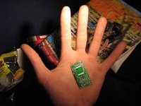
As always a big thanks to Jan for making the Amp 32 Kits. They are truly the smallest amps available. If someone has made one smaller, I'd like to see it. For only $25 US you can't beat the price if you can solder SMD/SMT.
Anyway here are some pics
http://s101.photobucket.com/albums/m59/Xspunge/?
and the website where you can get this amp is
www.41hz.com
Trying to get the amp into the case was harder than I thought. Trying to come up with a logical layout and clean looks was a little frustrating, and took a couple of tries. I had to desolder the original wires, cut them down, and when I found out they still wouldn't fit I had to go with even smaller gauge wires.
I tried going with an even smaller case, but it wouldn't allow me to mount the speaker terminals, or leave enough room for my voltage regulator.
The kit went together somewhat easily. I was sent the wrong instructions (I received the one for the original Amp 3 which is larger and has a different layout), so I tried to solder this kit using outdated info. Its pretty similar, but there are a few differences that slowed construction time way down.
Some of capacitors are numbered differently so it was up to me to figure out where they went. The diodes are also laid out different on the two boards so my amp did not work on my first power up attempt. Some minor gripes I had are that the soldering holes for the speaker outputs and power source are quite small. You can only use something like 20 gauge, or at the very most 18 gauge. The holes for the jumper/mute switch and LED are even smaller so that you have to use 24 gauge wires. Also, I do wish that the resistors were all of uniform size. The kit uses smd resistors that are two different sizes. It would have been nice if the board used the larger size resistors, but that might just be my personal perference. Also, I did happen to drop some of the caps and resistors a few times when trying to solder them. As always SMD and SMT things are a royal pain to try and find on the floor. Using a homemade hold down helped some, but things still flew off on their merry way a few times... almost never to be seen again. Thankfully they didn't fly far otherwise you wouldn't be reading this review.
So after finishing soldering the wires, I anxiously hooked it up to my speakers and mp3 player for testing. All I got was a faint repeated soft clicking noise.
After emailing Jan, he apologized for sending me the Amp3 instructions and sent me the correct AMP 32 instructions. After going over the new ones it turns out the diodes and their orientations are changed in the new amp. After changing their directions as specified in the new instructions the amp worked as promised and I got nothing but pure clean sound.
In regards to performance, it sounds very similar to my Amp 6 Basic. It is clear, with strong bass, and as expected sounded better than my baseline Sonic T Amp. And another important feature is that volume is increased Vs. the T Amp (although I will state that I increased the gain on all my amps in relation to the resistors given in the kits). I mainly use this for my portable speaker system and use my MP3 player as my audio source/preamp.
It does seem to have a little more bass than my Amp 6 Basic, but that just could be due to the 5% +/- variances in values given for resistors. I already knew what to expect in sound quality as many people rave about Jan's amps, and since I am a repeat customer of his, the sound quality came as no surprise. You won't be disappointed with any of his amps and if you are looking for something small, tiny, and has lots of power, and most importantly you can solder smt/smd then by all means get this amp. You won't find one smaller, cheaper, or better sounding for the price. And that is something we can all appreciate. If you cannot work with SMD/SMT then your best bet is go for the AMP 6 Basic since it is through hole based and the components are much easier to see and find. You will get the same great sound at sizes much friendlier on the eyes and fingers.
Anyway here are some pics
http://s101.photobucket.com/albums/m59/Xspunge/?
and the website where you can get this amp is
www.41hz.com
Trying to get the amp into the case was harder than I thought. Trying to come up with a logical layout and clean looks was a little frustrating, and took a couple of tries. I had to desolder the original wires, cut them down, and when I found out they still wouldn't fit I had to go with even smaller gauge wires.
I tried going with an even smaller case, but it wouldn't allow me to mount the speaker terminals, or leave enough room for my voltage regulator.
The kit went together somewhat easily. I was sent the wrong instructions (I received the one for the original Amp 3 which is larger and has a different layout), so I tried to solder this kit using outdated info. Its pretty similar, but there are a few differences that slowed construction time way down.
Some of capacitors are numbered differently so it was up to me to figure out where they went. The diodes are also laid out different on the two boards so my amp did not work on my first power up attempt. Some minor gripes I had are that the soldering holes for the speaker outputs and power source are quite small. You can only use something like 20 gauge, or at the very most 18 gauge. The holes for the jumper/mute switch and LED are even smaller so that you have to use 24 gauge wires. Also, I do wish that the resistors were all of uniform size. The kit uses smd resistors that are two different sizes. It would have been nice if the board used the larger size resistors, but that might just be my personal perference. Also, I did happen to drop some of the caps and resistors a few times when trying to solder them. As always SMD and SMT things are a royal pain to try and find on the floor. Using a homemade hold down helped some, but things still flew off on their merry way a few times... almost never to be seen again.
Thankfully they didn't fly far otherwise you wouldn't be reading this review. So after finishing soldering the wires, I anxiously hooked it up to my speakers and mp3 player for testing. All I got was a faint repeated soft clicking noise.
After emailing Jan, he apologized for sending me the Amp3 instructions and sent me the correct AMP 32 instructions. After going over the new ones it turns out the diodes and their orientations are changed in the new amp. After changing their directions as specified in the new instructions the amp worked as promised and I got nothing but pure clean sound.
In regards to performance, it sounds very similar to my Amp 6 Basic. It is clear, with strong bass, and as expected sounded better than my baseline Sonic T Amp. And another important feature is that volume is increased Vs. the T Amp (although I will state that I increased the gain on all my amps in relation to the resistors given in the kits). I mainly use this for my portable speaker system and use my MP3 player as my audio source/preamp.
It does seem to have a little more bass than my Amp 6 Basic, but that just could be due to the 5% +/- variances in values given for resistors. I already knew what to expect in sound quality as many people rave about Jan's amps, and since I am a repeat customer of his, the sound quality came as no surprise. You won't be disappointed with any of his amps and if you are looking for something small, tiny, and has lots of power, and most importantly you can solder smt/smd then by all means get this amp. You won't find one smaller, cheaper, or better sounding for the price. And that is something we can all appreciate. If you cannot work with SMD/SMT then your best bet is go for the AMP 6 Basic since it is through hole based and the components are much easier to see and find. You will get the same great sound at sizes much friendlier on the eyes and fingers.
Xspunge said:As always a big thanks to Jan for making the Amp 32 Kits. They are truly the smallest amps available.
Anyway here are some pics
http://s101.photobucket.com/albums/m59/Xspunge/?
this is great build.
gychang
Nice builds!
I've just recieved four amp32 kits, for me and some friends. Though I have a larger mc4x100 from audiodigit and heard a couple of TA 2020 based amps I am only familiar with the sonic t-amp when it comes to really small size. I am really curious to what the amp32 sounds like, can any of you share some more experiences compared to other amps?
I was thinking alu casing myself and keep them really small and light as I intend to use them portable too (on bikes, in cars and at the beach etc.).
I have to add Jan is a true sport and gave 100% support, also received the package really quick!
You'll love the AMp32. I just built my 2nd one and I added LED's to both. I know you asked about sound quality, but here is one tip, don't add the LED to the area specified in the instructions. I haven't been able to get one to light up at that location for some reason. I junked the small red one and went for a multicolor LED that changes R>G>B in intervals of 5 seconds, they fade out and the other color fades in. Very cool.
In any case, If you solder the LED to the power source input (but on the opposite side of the board, it is much easier to access, much easier to solder since you aren't next to the chip. And it still functions the same.
Another tip, increase the gain. the supplied resistors for the feedback loop don't have enough gain for MP3 players. Trust me on this one, I have increased the gain on all my 41Hz amps (2 Amp 6 Basics, and 2 Amp 32's). Instead of using the supplied 22k ohm in the R2 and R4 I used 10k ohm and used the stock 47k ohm resistors on the R5 and R6.
On my first one I used 22k ohm on the R2 and R4, and 68k ohm on the R5 and R6.
One other tip, you CAN fit 1206 size smt resistors if you feel like changing some of the values on the amp. The kit uses mostly smaller 805 size and the pads are sized accordingly. The 1206's are slightly longer and look to be too long to contact the pads, but they will fit. So if you don't have access to the smaller 805's and can only get 1206 size smt resistors, they will fit. The kit does use a couple of the 1206 size but not for the feedback loop/gain loop. It was pretty nerve wracking trying to squeeze a 1206 size resistor on the R5 and R6 pad then testing the board after finishing.
Also, you probably don't want to use both types of input caps (the 2.2uF smd caps and 3.3uF electrolytic caps) at the same time. The instructions say you can use both at the same time, but if you do, you get a really harsh turn on thump. So just choose one or the other (as you can see in the pic I chose the 3.3uF electrolytics)
So, finally, you will love the sound quality. It is outstanding and I cannot recommend it more. Most others are pretty impressed too, and usually even more so when they see how small the unit is. ONce you get yours done, and your friends do too, you won't be sorry, its great to have an amp as small as your MP3 player.
I am sure you could use off board resistors network, but since i haven't tried that I couldn't tell you how to do it. How high is the output level on your input source? You could always decrease gain by using the lower value resistors, i.e. 22k for both the R2/R4 and R5/R6 portions of the loop, or some other value if you need to go even lower.
Xspunge said:Anyway here are some pics
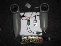
What exactly is going on with the driver placement on the iPod boombox? It looks like a dual 3-way set-up with the mids firing to the right & left, the woofers firing fore & aft, & the tweeter firing forward.
Just finished the first AMP32 I ever built, and it is working! Yeeeeehaaaa!
It's still in the test and burn-in period offcourse, but I can hear some really coherent sound coming from the little speakers. They try to keep up with the kickass bass signal from the little cute one...
It's still in the test and burn-in period offcourse, but I can hear some really coherent sound coming from the little speakers. They try to keep up with the kickass bass signal from the little cute one...
Attachments
Oh yes, one very important note on component mounting following order, don't place the 330uF caps before you placed the toroids!!
My Weller WTCP-S with standard solder tip didn't fit inbetween the toroids so I had to remove C18 before I could solder the last paw...
Unfortunately I damaged the cap in the process...
My Weller WTCP-S with standard solder tip didn't fit inbetween the toroids so I had to remove C18 before I could solder the last paw...
Unfortunately I damaged the cap in the process...

hey, xspunge,
what do you use for gluing acrylic sheets? I beed some badly.
in my amp32, I'm using three 3.7V 2.4Ah Li-ION cells from a canniballized laptop in series to get 11.1V (12.6V fully charged) and it lasts about two to three days blasting at full volume
imagine when I use the other cells wired at 11.1V 7.2Ah!
such big sound from a small package. everyone over here thinks it's a bigger amp!
planing on making a 2.5" full range driver in sealed or TL enclosures when the time permits.
v-bro said:Just finished the first AMP32 I ever built, and it is working! Yeeeeehaaaa!
It's still in the test and burn-in period offcourse, but I can hear some really coherent sound coming from the little speakers. They try to keep up with the kickass bass signal from the little cute one...
+1 for outside the box thinking!

djQUAN, you don't technically "glue" acrylic; you solvent weld it.
The solvent most commonly used is Methylene DiChloride.
Acrylic or Plexiglas is actually PMMA (Poly Methyl Meth Acrylate). When things
are built with it, it is generally not "glued" but solvent welded. With gluing
the adhesive itself forms the bond between the pieces and permanently stays the
re. Solvent welding actually works quite a bit different. The pieces of
Plexi are placed together in the desired fashion and the solvent is let to wet
or "bleed between the two pieces. They are then left to cure. What happens
is that the solvent dissolves the PMMA (in a small region). The long polymer
molecules from each piece entangle with each other while they are in solution
with the solvent. The solvent then slowly evaporates leaving behind a joint
of just PMMA with no adhesive.
The solvent most commonly used is Methylene DiChloride.
DJ Quan, the stuff here in the US is called IPS Weld On, don't know if they have that brand back in the motherland but yeah anonymous1 gave you the correct chemical name. Surely someone makes it over there.
Here it has several different viscosities, from super glue thin to syrup each with different setting times from a couple of seconds to a couple of minutes. I think they are called #3,#4, and #5 formulas.
In regards to the Li-Ion pack, as far as I know we are a few of the early adopters for using it for an amp.
Did you get the protection PCB? If not you should order one, and while you are at it get the "fuel gauge" which shows you the charge state of the battery.
check it out at
www.batteryspace.com look under li-ion cells, and you should find a link for them, or click on a cell and it should have a link near the bottom. You can see what it looks like hooked up on my battery. I shrinkwrapped it in clear to protect it and then silicone glued it to the outside.
It helps prevent overcharging and shuts off if the voltage drops too low.
Yeah my 4800mah li-ion pack runs for days at full blast. I usually have to charge it once every couple of weeks. It has 4 cells so I had to use an Lm317T, now it spits out 14.15v instead of the chip blowing 16.8 at full charge and yes... I have blown out an Amp 6 running unregulated. The battery blew a .25 inch hole in the chip (which I kept as a souvenir to my stupidity).
And in regards to to Speaker's question about my speakers... well I spent long hours contemplating the design, and after field testing with friends' iPod Hifi and Altec Lansing IM7, front firing speakers work great, but only if you are relatively in line with it. If you are running around or moving laterally you can't hear it and the volume drops off dramatically. With the side firing mids, at least you can now hear it on pretty much all sides. BTW I take it with me when I play football, soccer, softball, etc. So being able to hear it when you move is important.
I think I went more indepth on the answer on my post for it, don't know if it is still up but I listed it under CLass D "Zen Visionary speakers"
unfortunately, I got my cells from a laptop with a broken motherboard.
I now have twelve 2400mAh 3.7V cells. three wired in series for a smaller pack giving 11.1V at 2400mAh and when I need longer run times, I use the other nine wired in series-parallel for 11.1V at 7200mAh.
I made a charger from basic components since all other charge controllers on the net use a dedicated IC for that. I found a datasheet showing how to properly charge Li-ION cells and found out how important it is to follow the four step process.
the nine cell battery packs quite a capacity that I still haven't discharged it halfway ever since I took it out of the laptop and fully charged it once.
- Status
- This old topic is closed. If you want to reopen this topic, contact a moderator using the "Report Post" button.
- Home
- Amplifiers
- Class D
- Amp 32 Pics + Review