I have soldered and tested the wiring from line cord/fuse/switch/toroid/rectifier board. Works like a champ with one side at +27.3 vdc, the other at -27.3 vdc.
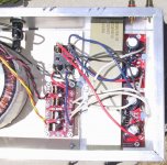
From rectifier board forward I have positioned the wires but not soldered yet.
V+ on rectifier board to fuse 1 then to V+ on both amps
V- on rectifier board to fuse 2 then to V- on both amps
(PG+ on rectifier board to PG+ on amp board) x 2
(PG- on rectifier board to PG- on amp board) x 2
Is this wired correctly?
Attachments
Looks OK. However, GROUNDING;I would jump PG+ and PG- on rectifier board with a thick wire and then connect this point to the chassis. Remove the local connection to chassis from each amp board. Or, you could try it the way you have (nothing willl blow up). If you get hum, do it like I described above ")
The way you have connected it works best if you use one transformer/rectifier per channel.
The way you have connected it works best if you use one transformer/rectifier per channel.
BrianDonegan said:Why connect the amp's power ground to the chassis? All it's gonna do is introduce the possibility of ground loops. I see no advantage.
Connecting the Mains Ground to the chassis makes sense from a safety perspective, but why would you connect the amp's ground to that?
It is common practice. Nothing to to with star grounding, the 0V point is between PG+ and PG- when powering 2 (or more) channels.
1. For safety. (Not such a big deal with +/-30VDC, but what if it was +400V?)
2. Shielding, by making the chassis the same potential as circuit ground, RF will be shunted to ground before reaching the signal path (hopefully).
Yes & No. Where do you return your star?Mad_K said:It is common practice. Nothing to to with star grounding,
RDV
Sorry, not trying to thread hijack...
Please explain. The mains ground to chassis provides the protection from electrocution. Not sure how adding the PS ground or signal ground to the mix changes this.
Would not the earth grounding provide shielding, and a path for RF shunting that would not include the signal path?
1. For safety. (Not such a big deal with +/-30VDC, but what if it was +400V?)
Please explain. The mains ground to chassis provides the protection from electrocution. Not sure how adding the PS ground or signal ground to the mix changes this.
2. Shielding, by making the chassis the same potential as circuit ground, RF will be shunted to ground before reaching the signal path (hopefully).
Would not the earth grounding provide shielding, and a path for RF shunting that would not include the signal path?
RDV said:Yes & No. Where do you return your star?
RDV
Not shure I understand your question. The star is between PG+ and PG- on the rectifier board. This is the star point. All grounds return here.
BrianDonegan said:Sorry, not trying to thread hijack...
Please explain. The mains ground to chassis provides the protection from electrocution. Not sure how adding the PS ground or signal ground to the mix changes this.
Would not the earth grounding provide shielding, and a path for RF shunting that would not include the signal path?
Lets say your preamp runs on 400VDC and is not connected to the chassis. V+ comes in contact with the chassis. You are touching a rca ground with one hand and the chassis with the other...

With 0V connected to PE the main fuse would blow if V+ shorted to the chassis.
Yes, you are right about RF shunting to PE with out connecting it to the circuit, my bad
But not if you have a class II product (not connected to PE)
Mad_K said:Looks OK. However, GROUNDING;I would jump PG+ and PG- on rectifier board with a thick wire and then connect this point to the chassis. Remove the local connection to chassis from each amp board. Or, you could try it the way you have (nothing willl blow up). If you get hum, do it like I described above
The way you have connected it works best if you use one transformer/rectifier per channel.
I understand the recommendation to connect PG+ and PG- together on the rectifier board, then one wire from here to star ground. Then do not use the star ground connections on each amp board. Is any one else doing this or does any one else agree with this?
Before changing what I have shown in the picture to follow this recommendation, I am trying to understand why the briangt lm3875 boards call for the wiring I show when your argument is to change it.
Any opinions will be appreciated, and then I will proceed with the wiring. I am looking to understand:
Why would the briangt design not call for this method?
Is the idea that it is forcing the zero voltage point at the earliest stage as well as making the star ground early rather than later?
But when I measure the voltage on the rectifier board (without the amp boards in circuit) it already ready + on one rail and - on the other (I cant understand how one side is negative when the two rail grounds are not tied together).
ransom peek said:
Why would the briangt design not call for this method?
.
Because the way he has done it is optimal when using one transformer/rectifier per channel (dual mono).
When using just one rectifier and still wiring it like you have done you are creating a ground loop. The significance of this will depend upon the wire lenghts/thinkness. In your case they are short and thick and looks like it would work OK without modification.
I would try it like you have first, then get used to the sound. Then I would change it over to the way I described. Notice any sonical changes?
ransom peek said:
(I cant understand how one side is negative when the two rail grounds are not tied together).
Because they are rectified. This has simply to do with the fact that you are reversing your probes when measuring from PG+ to V+ and PG- to V-.
If you are measuring from PG+ to V- you'll get 0V.
All of this assuming you have not connected the amp boards.
V+ comes in contact with the chassis.
This is why you have a fuse. Remember, your chassis is connected to earth ground.
BrianDonegan said:
This is why you have a fuse. Remember, your chassis is connected to earth ground.
But what if earth ground is not actually earthed?
BrianDonegan said:
This is why you have a fuse. Remember, your chassis is connected to earth ground.
But the secondary voltages are floating (transformer coupled) and the fuse will not blow if the circuit ground (0V) are not connected to the chassis.
Peter Daniel said:
But what if earth ground is not actually earthed?
This will be the same as it is not connected, ie. the equipment must be up to class II isolation. The fuse will blow if V+ shorts to the the chassis and the chassis are connected to 0V. The fuse will not blow if AC Live/neutral shorts to the chassis. Then again, this will only be dangerous if you touch equipment that are connected to PE.
The "belts and suspenders" method is to utilize both chassis grounding/PE connection and class II (double isolation). It also helps in getting FCC/IEC approval
some good reading:
http://www.conformity.com/
http://www.conformity.com/0308product.pdf
Anyone planning to relase/produce consumer equipment should know the IEC 60065 standard.
http://www.conformity.com/
http://www.conformity.com/0308product.pdf
Anyone planning to relase/produce consumer equipment should know the IEC 60065 standard.
Nordic said:I think Rod Elliot has the right idea (as usual)
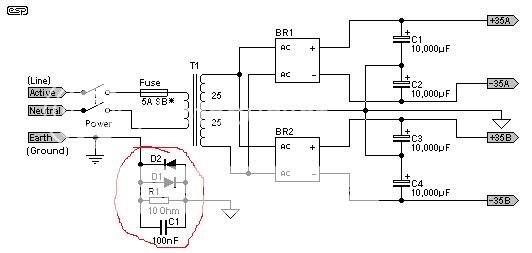
This will be the same scheme as I descibed, but with added ground loop/RF suppression (red circle)
Mad_K said:
Because the way he has done it is optimal when using one transformer/rectifier per channel (dual mono).
When using just one rectifier and still wiring it like you have done you are creating a ground loop. The significance of this will depend upon the wire lenghts/thinkness. In your case they are short and thick and looks like it would work OK without modification.
I would try it like you have first, then get used to the sound. Then I would change it over to the way I described. Notice any sonical changes?
OK, I'm going to wire it the way Mad K recommends (not my way first - I have confidence in the Mad K man), then wire the 2 inputs and speakers and fire it up - left hand in my pocket, fire extinguisher by my side.
The fuse will not blow if AC Live/neutral shorts to the chassis.
The mains fuse/breaker will...
- Status
- This old topic is closed. If you want to reopen this topic, contact a moderator using the "Report Post" button.
- Home
- Amplifiers
- Chip Amps
- LM3875 circuit ready to solder?