Mad_K said:Looks OK. However, GROUNDING;I would jump PG+ and PG- on rectifier board with a thick wire and then connect this point to the chassis. Remove the local connection to chassis from each amp board. Or, you could try it the way you have (nothing willl blow up). If you get hum, do it like I described above
The way you have connected it works best if you use one transformer/rectifier per channel.
So tie PG+ (both points= and PG- (both boints) together and to the 4 white leads to the amps?
Is this the recommendation?
Or better yet, tie each of the 4 white leads to the 4 rectifier board holes PG+, PG+, PG-, PG-, leaving about 1/4 inch insulation removed, then run a heavy wire across all 4 wire ends where they attach to the rectifier pcb so they are all tied together and also tie to star ground. Yes?
Attachments
Or better yet, tie each of the 4 white leads to the 4 rectifier board holes PG+, PG+, PG-, PG-, leaving about 1/4 inch insulation removed, then run a heavy wire across all 4 wire ends where they attach to the rectifier pcb so they are all tied together and also tie to star ground. Yes?
Nope, but you are on the right track.
The point of a star ground is that each grounded element has it's own, unfettered line to ground. (this is said a little simply, but) The central point help keep junk returning on ground from affecting the other grounded points (input, output etc). Also, it provides (ideally, but best you can do) a ground to all points with the exact same potential (a common ground).
Not exatly how I would do it, but I suppose you could use that big piece or wire as a ground bus and you star ground. Just solder all ground point to it. Not exactly a star, but not bad. Try it. If you have problems/noise, well, you get to rerun your grounds. Just like building another amp
") Its fun!
Its fun!BrianDonegan said:
Nope, but you are on the right track.
The point of a star ground is that each grounded element has it's own, unfettered line to ground. (this is said a little simply, but) The central point help keep junk returning on ground from affecting the other grounded points (input, output etc). Also, it provides (ideally, but best you can do) a ground to all points with the exact same potential (a common ground).
Not exatly how I would do it, but I suppose you could use that big piece or wire as a ground bus and you star ground. Just solder all ground point to it. Not exactly a star, but not bad. Try it. If you have problems/noise, well, you get to rerun your grounds. Just like building another amp
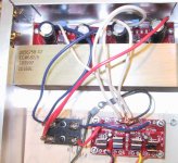
But isnt my picture showing the revised wiring plan what Matt K is recommending?
BrianDonegan said:Sorry, didn't look at the pic.
That looks good. Now just tie the RCA GNDs and Speaker Output Grounds there two for a complete star.
Though, I actually think you will be okay using the points on the amp boards as instead.
OK, so I go with my second photo following mad ks idea. Then I tie each input and speaker ground (where connectors are mounted to chassis) to the star ground, so all together I have 6 lines to star ground - line cord ground, rectifier board, 2 input signal grounds, and 2 speaker grounds.
The input and speaker grounds also go to the amp boards, right?
On the amp boards, is SG the input signal ground, N the input signal, OUT the speaker, and OG the speaker ground?
ransom peek said:
So tie PG+ (both points= and PG- (both boints) together and to the 4 white leads to the amps?
Is this the recommendation?
Or better yet, tie each of the 4 white leads to the 4 rectifier board holes PG+, PG+, PG-, PG-, leaving about 1/4 inch insulation removed, then run a heavy wire across all 4 wire ends where they attach to the rectifier pcb so they are all tied together and also tie to star ground. Yes?
Yes, just solder it like you have done it on the picture. As long as you have a good soldering iron that can manage soldering that massive copper junction
Just wire the RCA and speaker return grounds to the amp boards, nowhere else.
- Status
- This old topic is closed. If you want to reopen this topic, contact a moderator using the "Report Post" button.
- Home
- Amplifiers
- Chip Amps
- LM3875 circuit ready to solder?