My 18th birthday was a couple of days ago so I decided once school is out for winter break I will build my first tube amp. For years I've been wanting to build a tube amp and finally I'm gonna try out my first one.
I recieved the kit today in the mail and am very excited. It was only$150 for the kit and shipping. I'm going build a hopefully somewhat nice chassis for it, I'm not very good with chassis, but I'm gonna try my best. To do this I'm going to have to mount almost all the components upside down. When I ordered the kit they told me that this is a different design. Its slightly changed and uses different tubes, 10GV8. I like Volt Second's modifications, but I'm afraid they won't work with the new kit. I was wondering if anyone else could help me.
Here are some pictures.
Thanks,
Josh
An externally hosted image should be here but it was not working when we last tested it.
The kit looks rather easy to build, and I want to upgrade some components. I've already orded an ALPs pot for it and am willing to upgrade pretty much everything. I also have some solid core pure silver wire to wire the RCA and binding posts. I was making an order from another website for a chassis for another project so I added the pot, binding posts, RCA jacks, and the pot.
Other upgrades I was thinking about making were upgrading to nicer caps. There are 220uf, 22uf, and 100uf caps that I was thinking about upgrading.
The Voltsecond modifications I was interested in doing were: Ultrafast diode between diode bridge and first cap; .01uf recitfier noise cap; and 1uf snubber caps on each tube (really unsure about this one).
Any comments on which mods or updates will work?
An externally hosted image should be here but it was not working when we last tested it.
Hey,
I don't see any reason why you can't do the modifications he has listed, BUT i would replace the bridge rectifier with ultrafast diodes and not just add the one ultrafast as this means you dont need to cut the trace. The other mod i would sugest you look into that he has published on his site is to replace the power supply capacitors. who knows though, i may be wrong.. not familiar with that tube,
Owen
edjosh23 said:...The Voltsecond modifications I was interested in doing were: Ultrafast diode between diode bridge and first cap; .01uf recitfier noise cap; and 1uf snubber caps on each tube (really unsure about this one).
Any comments on which mods or updates will work?
All the mods should work fine as they are not specific to any tube type or operating point. I built this kit (or rather the regular S5 kit) a few years ago and incorporated most of Voltsecond's mods. I still listen to it regularly, it is a nice little amp.
I also soldered all the components except the tube sockets (and some resistors, I still can't remember why I did that
 ) on the "wrong" side of the circuit board. Just be sure you get good solder connections and everything should be fine.
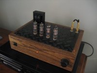
I also put in a selector switch so I could connect four sources. I put everything in a Padauk wood case with a thin aluminum top plate. Nothing is actually mounted on the plate, it just covers up the circuit board. Here is a photo of the case I built without the top mounted.
Attachments
I bought and built this kit, and I just finished doing a slew of mods from VoltSecond's site. I'm 23, and it is my first tube amp of what I hope are many more.
The 10GV8s don't matter as they have virtually the same electrical readouts as the 11ms8 (found that from another forum). I'm thinking about replacing my current 11MS8's with the 10Gv's soon just for kicks.
Other tips: if you plan on upgrading the electrolytics, don't drop in the stock caps. I'm happy with the upgraded beef (I ordered the exact ones recommended by voltsecond), but removing the old ones was a pain in the a** because of how thin and cheap the PWB and traces are. I ended up having to wire the new caps point to point using the schematic because in the desoldering stuff got tore up. Of course, I had never soldered before I put the amp together the first time, so if you're careful maybe you'll be ok.
If you do nothing else, remove the two resistors on either side of the pot and just use decent guage wire in their place. That's the change that I feel made the biggest (and best) improvement in the sound of the amp.
Good luck with your amp and happy DIY'ing. Let us know how things turn out.
Thanks for the replies.
Wow, I'm very happy to hear the all the mods will work.
ervington,
Thanks for the tips. I'm guessing you meant the two caps on either side of the pot, as GG describes on his website.
What caps did you buy? I don't remember voltsecond recomending any specific caps on his website? Should I replace the .22uf caps with Kimber Kaps or something as well as the three caps I mentioned earlier. I'm going to go online later and order hopefully some Elna caps to replace the cheap ones mentioned in my second post.
nikita,
I bought the amplifier directly from S-5 Electronics. On their website they have a phone number. I called that number and completed the order in about 10 minutes and got a tracking number. Shipping from Arizona to Georgia isn't so far, but $10 for shipping is pretty good.
Sherman,
You amp is very pretty.
I haven't decided yet, but my amp is probably going to have a copper front, back, and top pannel. The sides will hopefully be a pretty wood. The board will be mounted under the copper top, but using .5" stand-offs my solder joints should touch the copper. The traffo's will be mounted under inside the chassis.
I haven't decided, but I don't really want to tun my RCA and binding post far from the circuit board. I want to keep interference low so I think the RCA's will be mounted on the front and I think the binding post my be mounted right above the PCB, on the top plate. This is not the most convenient way, but I think interference should be lower with much smaller signal length.
thanks,
Josh
nikita said:EDJOSH
Thanks for answering. On the S-5 web they refer to the amp as k-12 M and you to K-12 G so...? Which is the latest? Beware when using copper unless you like to shine/buff every week!!! BTW I'm living in Canada not Georgia. Good luck!
nikita,
I live in Georgia. They advertise the K-12M, but they selkl the K-12G (the new one). If you call them they can explain the differences. The K-12G is brand new and I think they just haven't updated their website.
Will I really need to poish it that often?
Josh
Josh,
I did mean the caps (not resistors) on either side of the pot...I removed them a while ago and forgot.
Due to my inexperience, I just copied off other folks on the web. I used the Nichion electrolytics that Voltsecond recommended in his section on B+ Beef (he gives you the part #). I also used the same film foil .22uf caps as this guy:
http://ca.geocities.com/gmilitano/Tubes/K-12M/K-12M.htm
to replace the coupling caps. I know it's not creative, but I just wanted to see what kind of difference a proven part made before I played around. I imagine anything will be better than the stock caps. The guy who runs that site was also involved in this thread
http://www.diyaudio.com/forums/showthread.php?threadid=48568&highlight=
which was very long, also a little tough to absorb at times for me, but worth a read if you have the time. It's all about this kit.
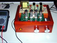
Below are pics of my ghetto amp...I plan on putting it in an enclosure over my christmas vacation. I wish I had known enough to plan on putting it in one from the beginning. Also, my dad is building the original without mods, so I'll have a chance to put mine up against his and really see what kind of difference all the mods make.
Good luck. Oh, and if you intend to play with it after plugging it in, remember that there is no safety bleeder on this circuit, and those caps store up quite a punch.
http://static.flickr.com/20/71897779_1c71aa2c9d_b.jpg
http://static.flickr.com/20/71897778_59a142333b_b.jpg (notice the jerry-rigging I had to do...don't be sloppy!)
I did mean the caps (not resistors) on either side of the pot...I removed them a while ago and forgot.
Due to my inexperience, I just copied off other folks on the web. I used the Nichion electrolytics that Voltsecond recommended in his section on B+ Beef (he gives you the part #). I also used the same film foil .22uf caps as this guy:
http://ca.geocities.com/gmilitano/Tubes/K-12M/K-12M.htm
to replace the coupling caps. I know it's not creative, but I just wanted to see what kind of difference a proven part made before I played around. I imagine anything will be better than the stock caps. The guy who runs that site was also involved in this thread
http://www.diyaudio.com/forums/showthread.php?threadid=48568&highlight=
which was very long, also a little tough to absorb at times for me, but worth a read if you have the time. It's all about this kit.
Below are pics of my ghetto amp...I plan on putting it in an enclosure over my christmas vacation. I wish I had known enough to plan on putting it in one from the beginning. Also, my dad is building the original without mods, so I'll have a chance to put mine up against his and really see what kind of difference all the mods make.
Good luck. Oh, and if you intend to play with it after plugging it in, remember that there is no safety bleeder on this circuit, and those caps store up quite a punch.
http://static.flickr.com/20/71897779_1c71aa2c9d_b.jpg
http://static.flickr.com/20/71897778_59a142333b_b.jpg (notice the jerry-rigging I had to do...don't be sloppy!)
EDJOSH
Regarding the copper plate, see that thread and look for Mark !You can also search for copper plate or copper chassis for more advices!!! As far as I'm concerned I wont touch copper!
Copper plate
Regarding the copper plate, see that thread and look for Mark !You can also search for copper plate or copper chassis for more advices!!! As far as I'm concerned I wont touch copper!
Copper plate
ervington,
I've read GG's website a couple of time, but never his thread.
The thread was a bit over my head, but I did manage to learn a lot from it. I did some searching and I believe the new tube that they are using at S-5 that I have is the 10GV8 is similar to the 6GV8 that is discussed in the thread and hopefully will help some of the issues mentioned.
I see you did some wiring underneith, but I can't figure out what it is for. On VoltSecond's website he mentions conneting pin 4 from tube 1 to pin 4 on tube 4, and connecting pin 5 from tube one to pin 5 on tube 4. You didn't seem to do this. Also, I have 20awg silver wire instead of 22awg, do you think it matters much?
VoltSecond recomends adding a UF diode between the rectifier and the first cap, but on the other thread blackie recomends changing the diode bridge to FREDs, but I can't seem to find how the layout is on those diode and whether or not it is a drop in mod or I need to change things around.
I also read some about changing out the traffos, should I change them or no? I'm willing to spend more money, but not too much.
nikita,
Perhaps I should try another type of metal. I love the way copper looks, but the volume knob I have doesn't go with copper anyway. At the metal store I'll see what they have.
Thanks,
Josh
Before you drop more tubes in, you should probably look up the spec sheets to make sure they have the same electrical readout...they might be "similar" but need slight tweaking in the circuit to get them to run right.
The wiring underneath was because I damaged some traces when desoldering the original electrolytics, not any real mods. Shortly after that picture I added filament snubber capacitors and the ultrafast diode. Voltsecond shows how to replace the diode bridge completely, but it was easier to just scratch out the trace and add one diode.
I imagine your silver wire is great, probably better. That's the kind of stuff that will make yours unique.
As far as traffos...if you have the money I hear upping to the Hammond 1608's will make a huge difference, and I have been told on another thread that at this point I'm quite limited by the original output transformers.
Packing for a trip to Phoenix....maybe when I get back you'll be on your way to a finished product. gl
erv
ervington,
Thanks for the help. I'll look into the Hammond 1608s.
I wasn't talking about replacing the tubes. When looking up spec sheets a website sent me from the 10GV8 to the 6GV8 page saying that they were similar. In the other thread they said that the 6GV8 was better.
Anyway, I'll go with the single UF diode.
I've got quite a few things to order before I begin building and I need to start getting pieces together for the chassis, hopefully this will be a nice one, haven't had much luck.
On of my last question was if there is aything wrong with mounting my traffos upside down. The stock traffos are pretty ugly and I don't want to show them off, but I want to mount the entire kit to the top of the chassis and for that to be possible I need the mount the traffos upside down. Any issues with that?
Hopefully by the time you come back I'll have more picutres and HOPEFULLY a really good review of the amplifier.
Thanks,
Josh
That looks nice.
Well I didn't want any of the traffo's to be seen, and I thought it perhaps woud be impossible to mount them on the bottom of the chassis because of the lenght of the leads coming from the traffos.
Would it be alright to mount the traffo's upside down if I cut slits so that some heat could escape?
by the way, What is the top of your enclosure made out of? It doesn't oxidize when not painted does it?
Josh
K-12 and Heat
Yes, the power tranny does get hot. I figure it is a little on the small side. The tubes also get very hot, so it is a good idea to keep the power and output iron as far from the tubes as possible.
Upgrades that I reccomend - upgrade the bridge. 4 UF4007 can be put into the PCB without drilling/cutting. Remove the DC block capacitors. Upgrade the coupling caps to film/foil or polypropylene. snuber caps on the heaters and HV.
I've noticed that little changes to the PS make a big difference. Upgrading the PS caps (larger and better quality) seem like a good idea.
I also tried dampers and they made a very slight improvement. The $10 for dampers is likely better spent on capacitors.
I have read that resistor upgrades are not really worth while.
Have fun with the kit and do report back on the sound.
Cheers,
Gio.
alexistheo said:the power tranny gets HOT. mounting it upside down will probably hinder cooling too much. you can always paint it to help the looks. the output transformers can be enclosed. here's what i did with mine.
Yes, the power tranny does get hot. I figure it is a little on the small side. The tubes also get very hot, so it is a good idea to keep the power and output iron as far from the tubes as possible.
Upgrades that I reccomend - upgrade the bridge. 4 UF4007 can be put into the PCB without drilling/cutting. Remove the DC block capacitors. Upgrade the coupling caps to film/foil or polypropylene. snuber caps on the heaters and HV.
I've noticed that little changes to the PS make a big difference. Upgrading the PS caps (larger and better quality) seem like a good idea.
I also tried dampers and they made a very slight improvement. The $10 for dampers is likely better spent on capacitors.
I have read that resistor upgrades are not really worth while.
Have fun with the kit and do report back on the sound.
Cheers,
Gio.
GG,
So far I have 4 Audio Cap .22uf caps, Alps pot, and silver wire. The silver wire will be in place of the two input caps. I see the caps the VoltSecond recomeneded the Nichicon UVR2E331MRD 330uf caps from Digikey. I wanted to also buy the snubber caps from there as well. Any recomendations on which caps would be the best?
Do you think it will be alright to mount them inside the enclosure upside down if I have lots of "breathing" holes around the traffos? I am also going to put these holes around the tubes as well.
Any more recomendations?
Thanks,
Josh
- Status
- This old topic is closed. If you want to reopen this topic, contact a moderator using the "Report Post" button.
- Home
- Amplifiers
- Tubes / Valves
- Holiday S-5 K-12G