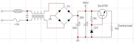
Heres my problem. I want to take 160VDC and bring it down to 12V to run a TL494 PWM, It's part of a high current(50A) 12V power supply I'm building for testing car amps on before putting them in the car. My problem is that no matter what I get for my theory it just doesn't work. I will show you my schematic at the bottom. I'm useing a basic series pass regulator with a zener holding it at 12V. when I have no load on the supply it will output 12V(not including losses) but the moment I put any load on it, the supply drops to .33 or so.
Could you please tell me what I'm doing wrong.
P.S I know I'm working with mains at the moment so that is why I'm asking.
 please see post #18 for additional information which assures me this isn't a suicide about to happen
Could you please tell me what I'm doing wrong.
P.S I know I'm working with mains at the moment so that is why I'm asking.
please see post #18 for additional information which assures me this isn't a suicide about to happenAttachments

ifrythings said:[snip]P.S I know I'm working with mains at the moment so that is why I'm asking.
ifrythings,
Man, you sure like to live dangerously. You realise this is a live mains circuit? And that you ground the mains through a diode?? As P-A said, get yourself a transformer. Otherwise you may need to change your name to ifrymyself .
Jan Didden
Not only dangerous but impossible. You want 12V at 50 amps? You'll never get that out of a mains supply anyway. Besides saving you from killing yourself, a transformer lowers the voltage and allows for increased current while maintaining efficiency.
Here is a correct approach.
http://sound.westhost.com/project77.htm
Here is a correct approach.
http://sound.westhost.com/project77.htm
This is NOT the correct approach. Using two separate windings, rectifying them separately and then paralleling them is very sub-optimal. There will always be a difference between the two winding voltages and diode thresholds. The shown diagram will result in one winding being more loaded than the other. (It is also unnessesarily expensive as it uses two bridges).
If you have two windings, put them in series, ground the midpoint and use two diodes from each end to get the pos (or neg) voltage. That divides the load over the windings close to 50-50. It also gives you a bit more voltage because there is only one series diode in the supply line instead of two. And it saves you 6 diodes or at least one bridge.
Jan Didden
Dude, you're INSANE!
My suggestion:
Get a battery charger from Canadian Tire with a starting circuit. My ages-old Motomaster charger has a 70A starting circuit. When it's in "start" mode, it puts out a regulated 12V, and really is good for up to 70A or so.
This will probably be cheaper than buying a transformer and associated bits to build a 600W 12VDC power supply, and it gets you something you can use for other things.
If the power coming out of the charger isn't clean enough, strap on a car battery in parallel. A motorcycle battery would do in a pinch, but DON'T charge it at more than 2A.
If that's not clean enough for a car amp, well, I'm not sure the alternator would be any cleaner.
Wes
That's the origin, I coined my current .signature one night after a marathon of UNIX systems programming. I've been using it since the late 90s.
Hiliariously enough, if you google for it, you will find that I have made a few people's quote files. I never thought I was quotable!!
Wes
Hiliariously enough, if you google for it, you will find that I have made a few people's quote files. I never thought I was quotable!!
Wes
ifrythings said:Heres my problem. I want to take 160VDC and bring it down to 12V to run a TL494 PWM, It's part of a high current(50A) 12V power supply I'm building for testing car amps on before putting them in the car. My problem is that no matter what I get for my theory it just doesn't work. I will show you my schematic at the bottom. I'm useing a basic series pass regulator with a zener holding it at 12V. when I have no load on the supply it will output 12V(not including losses) but the moment I put any load on it, the supply drops to .33 or so.
Could you please tell me what I'm doing wrong.
P.S I know I'm working with mains at the moment so that is why I'm asking.
Hey...
I like that circuit... hmm, lemmesee... (160-12)x50=7400 Watts of waist, hmmm.... very "frytening" I have to say... this must be a joke, very fun indeed and entertaining circuit idea though!

Cheers Michael
I think that nobody has understood the initial question, and I feel quite ashamed by such an amount of misunderstanding, particularly in a forum where SMPS discussion is quite usual.
ifrythings wants to power a TL494 SMPS controller IC directly from the 160V bus of his SMPS by means of a series pass regulator. That IC requires 12 to 20V to generate proper MOS gate drive signals and it draws approx 8mA when idle.
This is absolutely OK and is the solution adopted in almost all commercial SMPS units that feature primary-side control. It's quite obvious that an isolation transformer is required to do such SMPS development, but I assume that he has already got one, and if he doesn't, then he will be acting at his own risk (of death).
Also, the "transformer" shown on his schematic is not a step down transformer, it's actually the common mode EMI filter of his SMPS!!! Who could have missed that point???
Recommending a battery charger seems quite lame, because they are not regulated at all, they only provide crude current pulses. Furthermore, their "motor starting" feature is usually limited to 10 seconds (due to charger overheating issues) and provides very sharp (chopped sine!) current pulses, so it would probably destroy car-audio gear or the charger itself.
I have developed and built myself a 0-15V 0-120A adjustable power supply, and it's so happy powering small and medium sized car-audio amplifiers that it doesn't even require a fan (it's only required when powering several amplifiers at the same time during shows). There is a thread on that forum with a lot of data about my design. So go ahead with your project (and be very careful when dealing with high voltages).
The proposed circuit should work fine, altough you are going to get serious dissipation on the pass transistor if you try to get out of it more than those 8mA that the TL494 draws when idle. In most commercial units, this is solved by using the pass transistor during start up only, and then powering the control circuit from an additional winding in the main transformer when the supply is running.
For example, you can get 20V to 30V DC rectified from that additional winding (use the proper turn count), then pass them trough a simple L7815 regulator, and connect its output to the emitter of the 12V PSU pass transistor. When the SMPS is running the auxiliary supply will be forced to turn-off and the power will come from the 7815.
paulb said:Not only dangerous but impossible. You want 12V at 50 amps? You'll never get that out of a mains supply anyway. Besides saving you from killing yourself, a transformer lowers the voltage and allows for increased current while maintaining efficiency.
Here is a correct approach.
http://sound.westhost.com/project77.htm
Maybe he wanted to run only the 494 from that supply?
Or maybe not and he is already "ifriedmyself"
well, even then I would choose small auxillary transformer to supply 494 and other 12v circuitry, much more easy that way.
-----
BTW, that 100 ohm load is already pushing your pass transistor beyond its power limits. 10-20mA load might be reasonable but 120mA is too much. You also end up with 5watt power loss in your 5k resistor, if it not big >5w rated, its burnt already.
No Eva, there is no need for you to be ashamed. We others should be ashamed though, for misunderstanding. I guess we fooled each other into an increasingly deviating interpretation. 
However, as far as I know, Per-Anders is still right that forum rules dictate that this type of circuitry should not be discussed. Not everybody likes that rule, but that is another issue.
However, as far as I know, Per-Anders is still right that forum rules dictate that this type of circuitry should not be discussed. Not everybody likes that rule, but that is another issue.
Per-Anders is right, an isolation transformer is required in order to do that kind of experimentation with some safety. I have also mentioned it in my post. If a dedicated transformer is not available, several secondaries from standard transformers scrapped from old audio amplifiers may be connected in series in order to get an isolated 120V AC source. The thing should be also properly fused.
Here are some bits from another post of ifrythings that will clarify things:
dave
I currently work in a electronic repair shop fixing basic consumer appliances.
I have not took any major courses in electricity but I do know the safety inside out.
Hmmm so if I have this right, you guys thought I was useing raw mains with no isolation transformer? If this is correct then I'm sorry to everyone for not saying that I am using an isolation transformer (500VA) with a variac before it.
dave
Seriously, if you are interested in a solution rather than learning something, the best test power supply you can have is a battery and a battery charger. This must be the best cost effective solution.ifrythings said:Heres my problem. I want to take 160VDC and bring it down to 12V to run a TL494 PWM, It's part of a high current(50A) 12V power supply I'm building for testing car amps on before putting them in the car.
0.1-50 A, 12 V out, good effeciency and 120 VAC as input, safely build with low EMI/RFI is not a newbe task. One of the major problems is the transformer and how make it, not trivial unless you have good directions.
- Status
- This old topic is closed. If you want to reopen this topic, contact a moderator using the "Report Post" button.
- Home
- Amplifiers
- Power Supplies
- 12V Regulator problem