With slow baby steps I am going ahead with two sadhara-cubes.
Sealed design. 30 litres netto. Linkwitz transform down to 12Hz (natural resonance of the sealed design would be 42Hz).
Today I made some first measurements in order determine the
required power of the amp. I feel comfortable with +/-20mm excursion, or little more. The drivers are specified with a linear excursion of +/-27mm. (Well I measured bottoming at +/-25mm in one driver and +/- 28mm in the second driver)
For a 20Hz signal, I found that I will reach +/-20mm excursion already at 142V pp .
The required power was just around 390W. I had expected that I would need about double of the power.
Really nice! This will make the design of the class D amp and the SMPS easier.
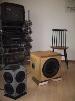
Here a pic of one cube.
Sealed design. 30 litres netto. Linkwitz transform down to 12Hz (natural resonance of the sealed design would be 42Hz).
Today I made some first measurements in order determine the
required power of the amp. I feel comfortable with +/-20mm excursion, or little more. The drivers are specified with a linear excursion of +/-27mm. (Well I measured bottoming at +/-25mm in one driver and +/- 28mm in the second driver)
For a 20Hz signal, I found that I will reach +/-20mm excursion already at 142V pp .
The required power was just around 390W. I had expected that I would need about double of the power.
Really nice! This will make the design of the class D amp and the SMPS easier.
Here a pic of one cube.
Attachments
Further on, I did some thermal examinations.
To get reliable values for the thermal speaker facts, the best way is to examine the RDC at a reasonable power level. Increase of RDC will give a clear information about the temperature of the voice coil. Fxxx on all power ratings given in any data sheet,
no matter which national/international standard they apply.
A copper coil will increase its RDC by 38% with every 100°C temperature rise. I applied a 10Hz sine wave with 40Vpeak-peak and monitored the DC resistance.
The initial value at 20°C was 2.77 W, after some hours it stabilized at 3.73 W.
According the temp. coefficient of copper this means about 91K temp rise of the coil, ==> running at approx. 111°C, which is not critical.
The power under this conditions was 43W.
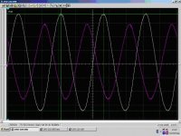
Below is the screen shot of the excursion test with 142Vpeak-peak and 390W. Under this conditions the voice coil heats up quite fast. Already after 10 sec. it exceeds 150°C .... well, I decided not to run it continuosly at this load...
White trace: Voltage across speaker, 20V/div.
Colored trace: Current through speaker (inverted polarity), 5A/div.
To get reliable values for the thermal speaker facts, the best way is to examine the RDC at a reasonable power level. Increase of RDC will give a clear information about the temperature of the voice coil. Fxxx on all power ratings given in any data sheet,
no matter which national/international standard they apply.
A copper coil will increase its RDC by 38% with every 100°C temperature rise. I applied a 10Hz sine wave with 40Vpeak-peak and monitored the DC resistance.
The initial value at 20°C was 2.77 W, after some hours it stabilized at 3.73 W.
According the temp. coefficient of copper this means about 91K temp rise of the coil, ==> running at approx. 111°C, which is not critical.
The power under this conditions was 43W.
Below is the screen shot of the excursion test with 142Vpeak-peak and 390W. Under this conditions the voice coil heats up quite fast. Already after 10 sec. it exceeds 150°C .... well, I decided not to run it continuosly at this load...
White trace: Voltage across speaker, 20V/div.
Colored trace: Current through speaker (inverted polarity), 5A/div.
Attachments
Hi Optical!
Well, the measurement is a simple mechanical set up with fixed
reference metal bar (must be quite solid to avoid bending) above the cone and a slide gauge.
No sophisticated optical system, sorry.
First I measure the distance from the reference bar to the
cone without signal.
Second, when the signal is applied, I measure again with the slide
gauge. CAREFULLY. You can hear it very clear, when the cone
starts touching the slide gauge. Difference of both readings is the excursion. Accuracy is limited of course, say about +/-0.5mm.
And furtheron I cannot see if the excursion towards the back
is identical with towards the front, as I only can measure the
outwards excursion.
But in order to get an idea about the required power, this
should be sufficient ....I guess....
Cheers Markus
error in first posting
...the unit for the RDC must be Ohms, not W !
The increase from 2.77 Ohms to 3.73 Ohms indicates an
temperature rise of littel more than 90°C....
How did the W get in that posting???
I took the text with C&P from a word doc... and there the unit is fine!!!
...the unit for the RDC must be Ohms, not W !
The increase from 2.77 Ohms to 3.73 Ohms indicates an
temperature rise of littel more than 90°C....
How did the W get in that posting???
I took the text with C&P from a word doc... and there the unit is fine!!!
Well it's a bad caracter table conversion, most of the time if you copy/paste PDFs you'll get W instead of ohms symbol.
Usually, Adire rate drivers with thermal ratings, so I'm surprised to see you're recommending less than 400W on this coil rated at 800W. I won't argue with you because you seem to know what you are doing hehe!
Usually, Adire rate drivers with thermal ratings, so I'm surprised to see you're recommending less than 400W on this coil rated at 800W. I won't argue with you because you seem to know what you are doing hehe!
Transform down to 12hz?
Why? Group delay would be terrible at that gain, it would also explain why your only able to use 400w to reach maximum excursion, in other words your seriously underusing the max SPL of these drivers but then again perhaps this doesn't matter.
I would have gone for transform to 20hz, you'd have higher power handling, low group delay and more SPL plus room gain would factor in and the natural 2nd order roll off of a sealed design would ensure a -3dB at 15/16hz. 12hz is useless unless played at high SPL which would then induce the whole room is moving feeling.
What if its already inaudible??Markus, good stuff -- always like to read your posts.
Sninobiwan, surely the whole point of Markus transforming down to 12Hz is to get the group delay and phase change down really low in the audible band?
What if all that filtering to fill in the response causes a similar response to a ported enclosure with its clearly known sharp cutoff near F3
By using the LT Markus is able to achieve a GD, phase and transient response that will be the envy of any vented box. The downside as mentioned is absolute SPL, but if it's loud enough for what he wants and his top criteria is ultimate accuracy... And don't forget just how tiny this sub is, this kind of performance is just not going to happen with a vented box even double the size.
richie00boy said:By using the LT Markus is able to achieve a GD, phase and transient response that will be the envy of any vented box. The downside as mentioned is absolute SPL, but if it's loud enough for what he wants and his top criteria is ultimate accuracy... And don't forget just how tiny this sub is, this kind of performance is just not going to happen with a vented box even double the size.
Note to self: Keep mouth shut until you've modelled it
Your right Rich, the GD is actually lower on the 12hz LT than either the 20hz LT or without EQ.
Actually it looks very good in the audible band, like I said above better.
Sorry Markus, I'll engage my brain next time I post
These look to be very good subs than despite my initial unfounded concerns.
And furtheron I cannot see if the excursion towards the back
hi
One reliable way to check +ve to -ve wave form and driver linearity is to
feed a sine wave - and pick up the signal with a microphone and feed the microphone signal to a scope
and enlarge the trace
you will be able to compare each half to the reproduced cycle
take care
suranjan das gupta
Quite a lot has moved here, while I had to work.
And thanks Richie:
You answered most of the questions, and also thanks
that you engaged me to go for a LT instead of ACE electronic some months back.
At Simon:
Yes, this driver already has a high power rating.
In fact Adire is stating 1000W max. per IEC 268-5.
Somebody told me that this standard would apply a noise
with a 6dB crest factor and check that the SPL does not drop
more than xx dB (3db? I don't remember...) after some hours.
From the 6db crest factor I would normally expect 250W thermal.
Hm, well even when taking into acoount the ventilation of the moving coil.... I have no idea how this should be possible without unsaint temperatures.
Imagine a ordinary light bulb, 60W. That's a lot of heat!
The entire bulb and fixture around is running quite hot.
From energetic view also a speaker is making heat only.
Some single percents (or less) of acoustic output can be neglected. So more or less all the power which you feed to it, will make heat.
Coming from this, I am always wondering about speaker
power ratings.
At Adire / Dan Wiggins:
Is there a reason why also respectable companies and
commitees for standardization are promoting strange
power handlings?
Or could I really drive the voice coil at - may be 300°C or higher ???
For copper that's no issue, also some wire isolations
could handle this.... , but what sort of killer glues would
you need for this? Even silicone based high temp glues
give up at 250° (from what I know)...
Regarding my power requirement of around 400W:
Adire themselves state that the power rating is the limit, not
the requirment. Furtheron they stated that usually much less will be sufficient to get full excursion. This is matching to my results.
Please not that I was talking about 20Hz with +/-20mm.
At 10 Hz, I require around 125Vpeak-peak. Required power is similar as at 20Hz, because the impedance is coming lower at 10Hz.
Hunter:
Yes, I think your proposal should work fine. Thanks.
P.S.
Somehow I feel this summer will give me some hard struggle with
the electronics and my girl friend....

Hi,
your magnet will become unzapped at much lower temperatures.
Alnico was one of the most heat resistant, but very few use it now.
Ferrite gives up at about 100degC from memory.
Maybe that is why they put the ferrite right out at the back, to avoid the worst of the heat!
your magnet will become unzapped at much lower temperatures.
Alnico was one of the most heat resistant, but very few use it now.
Ferrite gives up at about 100degC from memory.
Maybe that is why they put the ferrite right out at the back, to avoid the worst of the heat!
Are you sure about the 100°C ?
I thought hard ferrites for permanent magnet applications offer curie temp up to 400°C and could be used up to 200°C ( with
some reasonable drop of the flux density).
Thinking about small motors etc...
But I could be wrong, pemanent magnets are not my field.
I thought hard ferrites for permanent magnet applications offer curie temp up to 400°C and could be used up to 200°C ( with
some reasonable drop of the flux density).
Thinking about small motors etc...
But I could be wrong, pemanent magnets are not my field.
Lots more information about permanent magnet materials from Dan Wiggins and others in this thread: http://www.diyaudio.com/forums/showthread.php?s=&threadid=54110&highlight=
ChocoHolic said:
Really nice! This will make the design of the class D amp and the SMPS easier.
Have any good circuits for a smps of around 400W ?
thanks
Hi Thomas,
up to now just some basic thoughts.
http://www.diyaudio.com/forums/showthread.php?s=&threadid=54440
....now with about half of the power and probably I will chose the
following key components:
PFC-Boost: L6562 (PFC controler), STD17N80 (MosFet),
BYT30 (1000V) for boost diode
Push pull: UC3825A (PWM-controller), IRF1405Z (MosFets),
IR2113 (Halfbridge Driver), SPP 17N80 (MosFets for halfbridge)...
Still a lot of R&D ahead......
- Status
- This old topic is closed. If you want to reopen this topic, contact a moderator using the "Report Post" button.
- Home
- Loudspeakers
- Subwoofers
- JUST 142Vpp for +/-20mm excursion !