Same Kofi, new jam.
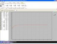
In the spirit of frugalphilia, I decided to use an old transformer I had laying around for Thorsten's phono pre project. I used a VOM to find the secondaries and the center tap, plugged it in and measure 290VAC. "Perfect!", sez Kofi. According to Duncan Amps PSU designer (see attached), that will work out to the 250VDC required for the project.
So, I assemble the power supply and I get 385 - 400VDC... and I say, "well, there's no load on the power supply right now, Kofi. You're scared over nothing. Just assemble it and I'm sure eveything will be fine."
Can you guess the rest?
Not fine. Not at all. I'm still getting about 385VDC fully loaded. So here's my question:
What the hell did I do wrong this time?
Please respond soon and help a brother out. Mrs. Annan is waling on eggshells and the dogs are hiding from me. I'm a peaceful man, really, but there are these times....
Help. Please help.
Yours in relentless ignorance,
Kofi
Attachments
Either your resistors are all off, your load is not 30 mA, your transformer is not the voltage you think it is, or you have found an exception to Ohm's Law. Now I know that you've been distracted recently with the Cotecna matter, but if you can get away from the press for a few minutes, I'd suspect the second- make sure you're actually drawing current. You should be dropping something like 35V across each of the resistors, which you can verify (carefully!) with a voltmeter.
Hi Kofi, how does the voltage across C1 compare to the PSUD2 prediction? That'll tell you pretty fast if the secondary was measured correctly. BTW, you may already realize this but, unless you're designing a fireworks display for the next UN jamboree, PSUD is predicting more than 4 amps of peak current through those nominally 1 amp rated 1n4007 diodes. Wouldn't want to see an international incident over it.
Having just made pretty extensive use of PSUDII when designing the PS for my new monoblocks I would have to say that it is pretty accurate. I modeled several different PS designs and actually built two. The end result was within a few percent of the predicted value.
How about taking out the constant current in your PSUD simulation and replacing it with a fixed resistor of a value you have on hand. See what PSUD says the voltage at that resistor should be then in your actual circuit put in that value resistor and check the voltage. If they are close then I think Sy is correct. Somehow you aren't drawing 30mA in your circuit.
BTW, did you ever get the electrician out to check out your other issue? Maybe you were checking the voltage on the trafo when your neighbor was running her blender!
")
How about taking out the constant current in your PSUD simulation and replacing it with a fixed resistor of a value you have on hand. See what PSUD says the voltage at that resistor should be then in your actual circuit put in that value resistor and check the voltage. If they are close then I think Sy is correct. Somehow you aren't drawing 30mA in your circuit.
BTW, did you ever get the electrician out to check out your other issue? Maybe you were checking the voltage on the trafo when your neighbor was running her blender!
Yipe! WTH's the 5 x fake transmission line for?
Two caps and a single resistor, or better yet inductor, works better than anything.
I would say your transformer and rectifier are obeying the laws of physics quite amicably. So the question remains, what did you screw up in PSUD?
Tim
WTH's the 5 x fake transmission line for?Two caps and a single resistor, or better yet inductor, works better than anything.
I would say your transformer and rectifier are obeying the laws of physics quite amicably. So the question remains, what did you screw up in PSUD?
Tim
Is it possible that I measured the AC wrong? I got about 285VAC in the VOM, but is could it be that I needed to measure peak voltage and not RMS?
According to the designer of the circuit, 30mA is about right for current consumption.
Also, I'm using FREDs for rectification rated at 6A, so the curent shouldn't be a problem.
Thanks for the advice. Any additional shoves in the right direction would be much appreciated. I'll run tests on the circuit tonight.
Kofi
Konnichiwa,
If your resistors are truely 1.2KOhm and not of a wrong value (eg 1R2 instead of 1K2) and your load is attached (a 5 - 8 Watt 240V incandescent lightbulb or two 110V <4 W ones in series may be employed as convenient test load, as might be a 8K2 resistor with at least 20W actual dissipation rating without heatsink) and confirmed to draw current, the voltage should pretty reliably fall into pace.
Sayonara
Kofi Annan said:So, I assemble the power supply and I get 385 - 400VDC... and I say, "well, there's no load on the power supply right now, Kofi. You're scared over nothing. Just assemble it and I'm sure eveything will be fine."
Can you guess the rest?
Not fine. Not at all. I'm still getting about 385VDC fully loaded. So here's my question:
What the hell did I do wrong this time?
If your resistors are truely 1.2KOhm and not of a wrong value (eg 1R2 instead of 1K2) and your load is attached (a 5 - 8 Watt 240V incandescent lightbulb or two 110V <4 W ones in series may be employed as convenient test load, as might be a 8K2 resistor with at least 20W actual dissipation rating without heatsink) and confirmed to draw current, the voltage should pretty reliably fall into pace.
Sayonara
Konnichiwa,
Reduction of ripple to absolutely miniscule levels using inexpensive and readily available, small value inexpensive capacitors.
I would suggest that you actually compare "lumping" the RC values with a multiple stage approach and you may to your surprise find that two caps and resistor or choke work MUCH WORSE.
Sayonara
Sch3mat1c said:Yipe!
Reduction of ripple to absolutely miniscule levels using inexpensive and readily available, small value inexpensive capacitors.
Sch3mat1c said:Two caps and a single resistor, or better yet inductor, works better than anything.
I would suggest that you actually compare "lumping" the RC values with a multiple stage approach and you may to your surprise find that two caps and resistor or choke work MUCH WORSE.
Sayonara
Kofi Annan said:... could it be that I needed to measure peak voltage and not RMS?
...
PSUD expects the trafo voltage as an RMS value. When you enter the voltage into the simulator it assumes it is RMS. You may have also entered an incorrect resistance value for the trafo but I don't think that would account for the amount of difference you are finding.
Also the RMS voltage of the trafo would be lower than the peak so if you used the peak value your resulting B+ would be lower than predicted by PSUD.
Kofi Annan said:I used a VOM to find the secondaries and the center tap, plugged it in and measure 290VAC.
Hi Kofi,
maybe it' s stupid question, but...
Did you measure 290 VAC from end to end or between an end and the center tap?
Cheers,
Bruno
Did you measure 290 VAC from end to end or between an end and the center tap?
Between an end and the center tap... why?
Why do I feel like the next response will cause me to projectile vomit?
Kofi
Kofi Annan said:
Between an end and the center tap... why?
Why do I feel like the next response will cause me to projectile vomit?
Kofi
So you actually have 580 VAC from end to end...
And you connected your bridge rectifier between the two ends, right?
Which is the voltage across the first cap?
I'm getting really confused. I checked and checked and checked the PSU, but I think its got to be OK. I checked the AC coming into the rectifier and I get 290VAC, which roughly equals the 400VDC I am seeing.
400VDC dropping to 385VDC means that, given the series resistors in the PSU totaling 4.8K, I'm only drawing about 3.1mA of current. That sucks.
I then noticed that none of the resistors in the PSU are dropping any voltage. Since V=IR, if I=0 or really close to it, it doesn't matter what R is, right?
So, I checked the current throughout various places in the circuit and it looks like there's no current being drawn at all. I honestly can't understand it and I'm afraid its going to kill me. I have measured voltage with the tubes both out and in and it doesn't seem to make any difference.
More problems: the filament for the first stage tube looks like its OK, but the second stage tube's filament won't glow. I checked the voltage and its hapily receiving a regulated 6.2VDC supply, but the its clear that it refuses to glow. Its actively working against me now. I can feel it.
Will I have to tear down and reassemble the circuit or are there any places I should start looking for the problem(s)? Oh, one more thing, the PSU caps seem to be recharging, even after they have been completely discharged. I have heard of this phenomenon before, but I've never experienced it.
Is this symptomatic of a common problem that can be fixed by simply soldering one joint together?
Didn't think so.
Please help. Before I kill. Again.
Kofi
Sorry... I;ve been so busy I forgot to answer direct questions.
No, I believe that I have it appropriately tied to one end of the secondary and the center tap. The AC measures about 290VAC on the rectifier.
I get 400VDC...
Kofi
So you actually have 580 VAC from end to end...
No, I believe that I have it appropriately tied to one end of the secondary and the center tap. The AC measures about 290VAC on the rectifier.
Which is the voltage across the first cap?
I get 400VDC...
Kofi
Check all your ground return leads for continuity
Will do. If there's no return, there's no current. Makes sense to me.
BTW, what are you using for a load?
Why, the circuit itself, of course. Bad idea, right?
Here's the circuit, by the way.
Any other advice or a request to come to the UN building and fix this yourself would be greatly appreciated.
Kofi
Try it again with a resistor to simulate the load.
Consider it done. Tomorrow, anyway.
By the way, PSU designer says that with a 3mA current draw, I'll get about 392V, which is almost exactly what I'm getting off the PSU right now. I bet its a ground.
Kofi
- Status
- This old topic is closed. If you want to reopen this topic, contact a moderator using the "Report Post" button.
- Home
- Amplifiers
- Tubes / Valves
- Kofi Annan in: "B+... PLUS!!!"