Oh no homer09, I have both Rev A and Rev B now I'll have to buy Rev C to keep my collection of BrianGT PCBs complete. 
BTW: What I'd really like is a experiementers PCB. Similar to the existing board as far as the LM3875 and caps are concerned but the connectors to the sides and a prototyping area in the middle. I wish I had a tenth of Brian's skills to design and make one. It would be nice if a LM3886 chip could fit as well. Hey, this is probably a good idea for digi01.
BTW: What I'd really like is a experiementers PCB. Similar to the existing board as far as the LM3875 and caps are concerned but the connectors to the sides and a prototyping area in the middle. I wish I had a tenth of Brian's skills to design and make one. It would be nice if a LM3886 chip could fit as well. Hey, this is probably a good idea for digi01.
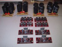
That is easely done on the rev.B boards! You actually have four holes for the caps 'onboard'. The zobel network would in either case be mounted at the output of the PSU. Assuming you are talking about the 'high-cap' PSU. See the pic.I would personally like to see the ability to add in the snubber caps CarlosFM has been talking so much about.
Steen.
Attachments
m0tion said:We could always turn this thread into a Revision C wishlist. Perhaps Brian and PD could get some ideas from it. I would personally like to see the ability to add in the snubber caps CarlosFM has been talking so much about.
the snubber caps belong on the diode board --
That is easely done on the rev.B boards! You actually have four holes for the caps 'onboard'. The zobel network would in either case be mounted at the output of the PSU. Assuming you are talking about the 'high-cap' PSU. See the pic.
steenoe,
What size/type cap did you use with the snubber?
widman
widman said:
steenoe,
What size/type cap did you use with the snubber?
widman
the size of the capacitor is related to the inductance of the secondary of the transformer, and the capacitance of the diode itself (this can be obtained from the manufacturer's data sheet).
when you measure the inductance make sure to short the primary leads.
The value of the caps is 100nF as recommended by CarlosFM.What size/type cap did you use with the snubber?
It is generic polyesterfilm caps. You could ofcourse consider more excotic parts, but how much is gained by that?
It is the same type 1oonF caps used at the output of the psu for the Zobelnetwork, as well as for bypass for the 100uF electrolytics on the board. Hope this helps
The small caps are not at all implementet as diode-snubbers.
Steen.
steenoe said:
The value of the caps is 100nF as recommended by CarlosFM.
It is generic polyesterfilm caps. You could ofcourse consider more excotic parts, but how much is gained by that?
It is the same type 1oonF caps used at the output of the psu for the Zobelnetwork, as well as for bypass for the 100uF electrolytics on the board. Hope this helps
The small caps are not at all implementet as diode-snubbers.
Steen.
100nF is a number pulled out of thin air -- with any value this high you dissipate energy through the snubber according to E= 1/2 (C*V^2) -- (not that it's a lot of joules, it's just a pointless waste of energy).
here's a homework assignment: using 100 uH for the secondary inductance and 100pf for the diode capacitance of an MUR860 at 30V determine the correct value of a snubber --
http://www.hagtech.com/pdf/snubber.pdf
I'm getting consistently good results with the values I recommend for the snubber, no matter what trafo or diodes I use.
Just found out another happy diyer:
http://gainclone.com/phpBB2/viewtopic.php?t=550&postdays=0&postorder=asc&start=0
Just found out another happy diyer:
http://gainclone.com/phpBB2/viewtopic.php?t=550&postdays=0&postorder=asc&start=0
hi homer09,
Any post NOT from BrianGT or Peter Daniel are going to be off topic, including this one.
and... I think BrianGT and Peter Daniel are now "smart" enough not to get involved in heated technical discussions that go round and round in circles. I use to love those threads.
I'm sure they will deliver a good product.
Any post NOT from BrianGT or Peter Daniel are going to be off topic, including this one.
and... I think BrianGT and Peter Daniel are now "smart" enough not to get involved in heated technical discussions that go round and round in circles.
I use to love those threads. I'm sure they will deliver a good product.
Hi Greg,
>It would be nice if a LM3886 chip could fit as well.
actually with an effort, LM 3886 can be fit also to the current PCB (rev A or B)... from the datasheet you can see that the first 4 pins of both chip is the same:
- no problem for the first 4 pin
- un-used the pin 5 on 3886 (since it is exactly the same as pin 1, as V+).
- Pin 6 is the same on both chip.
- don't connect pin 7 on 3886 to the board. Bend it out then run a wire from it to the star ground point.
- don't connect pin 8 on 3886 to the board. Bend it out then run a wire from it through mute resistor to the V- (pin 4, or somewhere else the same V- referenced on the board)
- bend pin 9 of 3886 to the board hole position of pin 8 of 3875 (this is easy)
- bend pin 10 of 3886 to the board hole position of pin 7 of 3875 (this is a bit diffcult). OR, you can also bend it out and wire a jumper to the hole position of pin 7 of 3875, or directly to the meeting point of R1 & R2 on the board (solder directly to the meeting point... the resistor leg)
Sounds complicated but actually easier to do than write...
My real wonder is actually whether LM3886 in Non-inverted mode will sounds better than LM3875. (Just my curiousity, despite the difference in power and current output, I seems mostly see LM3886 configured in inverted mode while LM3875 mostly configured in NI mode. So I figure out those must be an optimal setup for both the chips.)
Regards,
---
David
>It would be nice if a LM3886 chip could fit as well.
actually with an effort, LM 3886 can be fit also to the current PCB (rev A or B)... from the datasheet you can see that the first 4 pins of both chip is the same:
- no problem for the first 4 pin
- un-used the pin 5 on 3886 (since it is exactly the same as pin 1, as V+).
- Pin 6 is the same on both chip.
- don't connect pin 7 on 3886 to the board. Bend it out then run a wire from it to the star ground point.
- don't connect pin 8 on 3886 to the board. Bend it out then run a wire from it through mute resistor to the V- (pin 4, or somewhere else the same V- referenced on the board)
- bend pin 9 of 3886 to the board hole position of pin 8 of 3875 (this is easy)
- bend pin 10 of 3886 to the board hole position of pin 7 of 3875 (this is a bit diffcult). OR, you can also bend it out and wire a jumper to the hole position of pin 7 of 3875, or directly to the meeting point of R1 & R2 on the board (solder directly to the meeting point... the resistor leg)
Sounds complicated
but actually easier to do than write... My real wonder is actually whether LM3886 in Non-inverted mode will sounds better than LM3875. (Just my curiousity, despite the difference in power and current output, I seems mostly see LM3886 configured in inverted mode while LM3875 mostly configured in NI mode. So I figure out those must be an optimal setup for both the chips.)
Regards,
---
David
Hello,
As for the revision 3 boards (last ones were called revision 2), the current idea is that the changes will be minor, but if you have suggestions, please post them in this thread, and I will consider them.
Here is the current ideas for modification:
- slight modification for placement of zobel resistor to maximize ground plane
- modification of signal ground -> output ground trace to optimize ground interactions
As for the snubber capacitors, they can be soldered directly to the pins of the diodes, on the bottom of the pcb.
As for the idea for the LM3886 compatibility, it would be easier to just make a new pcb for it. I actually worked on one quite a few months ago, but there didn't seem to be as much interest in the LM3886. I could revive the design in the same fashion as the LM3875 boards if people are interested.
Happy Holidays to all. I have caught with the US orders and all but 1 are not shipped out, and I have started working on the remaining International orders. I should be completely caught up by the end of the week.
Also, I was straightening up my parts bins last weekend, and found enough components for 5 LM3875 premium kits. If people are interested, I will sell them for $75 each + shipping (for stereo version). Drop me a mail if you want to get one of the last kits.
--
Brian
Good to change the ground, now it will be perfect. You might also add an instruction for patching the signal ground at the present pcb's. My simple calculation points to an increase of the distortion of 0.02%. It my not be that much but with this minor change you have done what it's possible to direct the ground currents where they should go and not go.
Brian, I think you should consider to add every part on the pcb's which needs to be there becasue it will be easier for the builder to have holes to put the parts in, less sources to problems.
I'm quite sure you can get an interest for LM3886 also. If you do, add the mute option! If digi01 make and sell LM3886 pcb's, so can you
Brian, please add good schematics for your projects also!
This is more of a question but it could be a suggestion too.
I haven't yet built Brian's GC but looking at the manual I noticed that PCBs come joined, but scored, so that they can be snaped apart. I am not sure how the optimal implementation is intended to be - in the sense that - is it better to just leave the boards joined and use small jumper wires going from the rectifier board to the amp board ?
Otherwise if you break them up then I wonder if the long snaky wires running from the transformer to the rectifier board and then from the rectifier board to the amplifier board have anything to do with the power supply decoupling issues that arise when using high value filter caps, and apparently can be taken care of by the new(Carlosfm) impedance compensation/decoupling arrangement.
In other words would it help to have everything - i.e the psu and amp - onboard as one unit ?
I do have a few premium LM3875 stereo kits left. They will be $75 each, and include:
1 - revision 2 pcb set, containing 2 main boards and 2 rectifier boards
2 - LM3875TF chips
4 - Caddock MK132 21.5k resistors
2 - Riken 680ohm 0.5w resistors
2 - Caddock MK132 220ohm resistors
4 - Panasonic FC 1500uF caps
2 - Blackgate N 4.7uF non-polar caps (for rectifier board)
8 - MUR860 diodes (for rectifier board)
2 - 0.1uF polypropylene caps (for zobel network)
2 - 2.7 ohm resistors (for zobel network)
Shipping is $6 for US, and $11 for international. Drop me an e-mail if you are interested. I am not going to put up an order page, as I only have 4 kits left right now.
The bold entries indicate the upgraded components over the standard kits.
--
Brian
- Status
- This old topic is closed. If you want to reopen this topic, contact a moderator using the "Report Post" button.
- Home
- Amplifiers
- Chip Amps
- Brian's LM3875 REV C boards