I built 15 of Daniel Meyer's Tigersaurus' about 30 years ago and I still have them. Now I'm building up a couple of the Slone 400 watt opti-mos amps. Has anyone here built them? I'm curious to get some feedback on them but since I'm still in the fabrication process I hope the feedback will be good (but I want any feedback regardless of whether it's good or bad).
Thanks!
Thanks!
Attachments
Rarkov built the 200 watt optimos amp not the 400, however I doubt there is much difference between the two designs apart from more power. I have built two of Slones amp designs, both from the high power audio amplifier construction manual (is that right???). These were the 80watt, very low distortion amp, and the 200 watt PA amp. (Designs 11.4 and 11.8) Both of them sound brilliant, I dont really have any comparison for them as regards to other DIY amps or many consumers amps for that matter. But I can say tha both amps sound significantly better then a Quad77 integrated (£700). So much so that my parents asked me to build them a pair of the 200 watts with a matching pre amp, to replace their Quad.
Both are very smooth, but not at the expense of detail, on the contrary they are very detailed and transparent, with loadsa umph where its required. They never become harsh and fatiging, if the sound you get hurts its not the amps, unless ofcourse you cause them to clip, but thats another story. I would even say they have tube like trebble, but having never heard a tube amp this would be a bit of meaning less comparison! But all the "magical" tube sound I have read about in hifi mags, the decription matches rather well to what I hear.
The 200 watts have increadibly tight and controlled, tuneful bass. This is directly driving a peerless 850146 in a sealed cabinet of about 66 litres. The 200 watt is better in the bass then the 80 watt and I cant really comment on the mids and highs as I havnt really done any critical listening comparing the two amps. Thats kinda hard when your main speakers are three way fully active so you cant swap and change amps as you please, as you need them all to get a good sound! I will be doing a comparison however probably this weekend if I dont have too much work to do.
Bottom line is, I dont think you will have any problems with Slone amps, most of the DIY amps available are high quality designs which will give expensive consumer amps a good run for their money. Its probably all personal taste and I like the sound of the Slone amps, build one and I dont think you will be dissapointed, I have not been yet.
5th element said:Rarkov built the 200 watt optimos amp not the 400, however I doubt there is much difference between the two designs apart from more power.
AFAIK there are no different versions of it. You just add more
output devices and increase the rail voltage. It is designed to
be modular in that sense. Might affect the sound, though.
Hi,
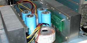
Both Christer and 5th Element are correct. I built the 160W OptiMOS but raised the rail voltages to achieve 180-200W. I will post some pics on my website before too long. I absolutley love these monoblocks. A couple of things that I've noticed is they are very resistant to power supplies...I have my PSU next to my amp PCB with no sheilding and there is not a hint of hum through the speakers. However, the chassis hums somethimes, but that is due to a lack of inrush protection...which cannot be blamed on the excellent OptiMOS.
200W produces amazing control in the bass and gives me exactly the signiture of sound that I'm after. It's perfectly balanced!
The 400W version is said to exhibit the 200W version's "same outstanding performance results". Randy Slone goes on to mention 6 bullet points of modifications. This require
Resistor changes
New rail voltages (+-85V)
New fuses (7A)
New MosFETs (SemeLab's Double-die BUZ901CDP & BUZ905DP)
New Heatsinks (0.2C/W)
The number of output devices stay the same (4 per channel) but the heat dissipation seems collosal for a Class B amp!
I would think you could build a 250-300W amp with little or no modifications to the circuit. It is very rugged. However, I would suggest modelling in PSpice and checking that no components exceed their rated specification.
Good luck and let us know how it goes! You'll be very pleased!
Thanks,
Gaz
revised schematics
Hi,
I've contacted Mr. Slone two weeks ago to get some answers on parts used in the OptiMOS design. His extreme friendly answer had revised schematics for the commercial versions (the ZUS-Amplifier) of the OptiMOS, both 200W/400W and a new 800W Version attached.
For obvious reasons I can't post them in this forum.
EE_Mark: maybe you should contact him directly? He seems to be a very nice and helpfull guy.
Re: revised schematics
I've talked to him on several occasions. Yeah, he's a real nice guy. I don't have any questions for him - I was just wondering if anyone here had built one of his amps and how they liked it. After reading the responses I'm more excited than ever to get mine completed!
MichaelB said:Hi,
I've contacted Mr. Slone two weeks ago to get some answers on parts used in the OptiMOS design. His extreme friendly answer had revised schematics for the commercial versions (the ZUS-Amplifier) of the OptiMOS, both 200W/400W and a new 800W Version attached.
For obvious reasons I can't post them in this forum.
EE_Mark: maybe you should contact him directly? He seems to be a very nice and helpfull guy.
I've talked to him on several occasions. Yeah, he's a real nice guy. I don't have any questions for him - I was just wondering if anyone here had built one of his amps and how they liked it. After reading the responses I'm more excited than ever to get mine completed!
ZUS audio
ZUS Audio Inc. is the company selling the Amplifiers.
See http://www.zusaudio.com but do not expect it to be a very exciting site...
ZUS Audio Inc. is the company selling the Amplifiers.
See http://www.zusaudio.com but do not expect it to be a very exciting site...
I've built a couple of his amps. Both were of the moderate power variety (125W or less). Single long tailed pair topology which I take to be Slone's variation on Self's Blamless amp theme. As a learning experience, I laid out the pcb's myself. It took me three tries and lots of learning. (I know know a bit more than before about parasitic oscillations and how to avoid them.) If you were to use Slone's PCB layout, I would not expect you to have the same problems (ore lean as much about parasitics) as I did.
I built these as parts of secondary systems (bed room and office). This was a mistake as I now prefer those two rooms for listen rather than my living room where amplifier duty is served by a 20+ year old Carver M400. Next major project is obviously an amp for the living room.
I'm leary to asign adjectives to the sound from an amplifier partly because of the over-blown prose one can read in high-end publications. Nonetheless, there is something about Slone's amps . . . . I guess they just sound real good.
I recently finished a pair of Opti-Mos boards and gave them a listen. In a word, OUTSTANDING!!! At least for my ears anyway. Because sound is subjective to the listener I won't tell you to rush out and build one but quite simply it is the best amp "my" ears have ever heard. Audio has been a hobby of mine for over 30 years and I've owned a listened to quite few amps. Briefly what I heard was the smoothness of a tube through the midrange and top end with the punch of solid state on the bottom.
If you like big power he has a new design coming out called the Totem Pole. 800 wpc. Also a new preamp is in the works.
Hope this helps.
Brad
If you like big power he has a new design coming out called the Totem Pole. 800 wpc.
Also a new preamp is in the works.Hope this helps.
Brad
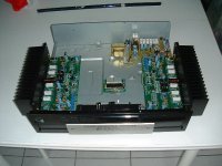
Yep - I built a dual mono version with dual power supplies and my own pcb - it doesn't look as nice as your's under the hood.
I had some problems with oscillation at first and blew an expensive tweeter. Got it to work with some help from Randy.
I also made a few circuit changes of my own. Fab sound now.
I had some problems with oscillation at first and blew an expensive tweeter. Got it to work with some help from Randy.
I also made a few circuit changes of my own. Fab sound now.
I had some problems with oscillation and hum. The oscillation might have been due to non-Hitachi devices, or using a self etched pcb. I got the MosFets from Rapid Eletronics in the UK but they were described as Hitachi so I don't know.
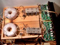
To elimante the hum I actually went to an extreme of building a dual mono supply with two torriodial transformers and rethinking the grounding and internal wiring. I learnt a lot about this sort of noise in the process and could probably go back to a single 500va 50-0-50 transformer - however given that it sounds superb the motivation to do so is low.
Elimating the oscillation was a lot harder. I tried all sorts of things, some still remain, however the eventual fix was simply to increase the size of R23 & R24 gate ressistors to 1k on the 2sk1058 MOSFETs. This looks unbalanced to me, given the gate resistors on the 2sj162 mosfets are only 470ohm. I've seen another approach which is to add a capacitor to even up the gate capacitances. Examples using a capacitor seem to use a range of values anywhere from 30-300pF. I don't know which is the better approach but would appreciate any advice on this subject.
Here's the link to the circuit that I built, it's actually dated 0ct 2001 and revision 2, the pcb is from his audio projects book.
http://www.sealelectronics.com/kits/images/OPTI1001.pdf
Before arrived at this solution I made some other changes in my hunt for the cause. I stripped out all the protection, converted the softclip VAS cascode bias into a standard zener regulated bias arrangement and changed the NFB take off point.
A few of my component values are also slightly different, e.g. 1000uF for C10 the NFB DC block capacitor, 220pF for C12 & 14 the larger of the miller compensation capacitors. I lowered the mosfet source degen resistors to 0.22 ohm, I read somewhere that lower is better (true or false?) but given that the mosfets appear to be not well matched I should maybe change them back to 0.5 ohm?
I lowered R3 & R14 to 4.7K to increase the zener current flow on the input stage cascodes because I wasn't seeing a stable 24V there.
I recently also increased the input resistance to 22k and have lowered the gain to 23x because my pre-amplifier is putting out quite a high signal.
I have a couple of questions about the circuit that puzzle me, I don't get why the collector resistor on the input stage cascode is 1k on the -ve differential input and 2.7k on the +ve input.
The differential tail currents also seem low to me, i.e. 0.6V/470 = 1.3ma and I'm tempted to lower R6 and R13. Many of the examples in his power amp manual have a higher tail current source of around 4ma or 2ma per leg.
Nick
I'm a total novice to amp design, so take all my remarks in that context.Nick Walker said:Elimating the oscillation was a lot harder. I tried all sorts of things, some still remain, however the eventual fix was simply to increase the size of R23 & R24 gate ressistors to 1k on the 2sk1058 MOSFETs. This looks unbalanced to me, given the gate resistors on the 2sj162 mosfets are only 470ohm. I've seen another approach which is to add a capacitor to even up the gate capacitances. Examples using a capacitor seem to use a range of values anywhere from 30-300pF. I don't know which is the better approach but would appreciate any advice on this subject.
I believe he's already mentioned the asymmetry in his book, where he says that this is needed to counteract the different junction capacitances of the N-channel and P-channel devices.
I bought the infopack of the OptiMOS from him, i.e. construction notes, parts list, PCB layout, etc. There, the parts list says "680Ohm (or 1KOhm)" for these resistors. I found that mention pretty strange, because I'd have thought that anyone wanting to play with the resistors would go in smaller steps, from 680 to 750, to 820, to 1K. Now that you mention your experiences, maybe Randy believes 1K is a good alternate value?
Incidentally, the notes he sent me contains the PCB layout for a single-sided PCB. But many constructors report that they've got a double-sided PCB from him. I guess he had both versions.
What's the heat dissipation like? Do the heatsinks get hot? Isn't it unusual for any Class B amp in "home listening" conditions to get more than slightly warm? Finally, it doesn't matter how big the amp is... for Class B, the dissipation should be proportionate to how much you're outputting to the speakers, shouldn't it?
But I'm really glad so many of you seem to really like the OptiMOS. I too have decided to build the "Fig 11.4 design" (an ultra-low BJT CF OPS design) and the OptiMOS. I'll need all your help once I start.
Did any of you guys use "audiophile grade" components like Caddock or Dale or whatever brand of OPS power resistors and so on?
The OPTI-MOS kit sound sounds very nice ") I bought two kits from him, however at the current moment my amp is totally naked and I'm too lazy to build a case...
I bought two kits from him, however at the current moment my amp is totally naked and I'm too lazy to build a case...
First project ever and I had absolutely zero problems... Components include low-esr Xicon caps and god-knows what resistor brand... (wouldn't think it matters). 1xKVA trafo & 30.000uf per supply rail/kit. The 1KVA trafo has the advantage that the rails do not get ANY chance to sag under load. It's stiff as a brick!
Mods: removed input caps* (better imaging!) & reduced gain to accomodate my preamp signal, soldered PS wires (and fuses in their slots ) directly to PCB which vastly improved things in the 'bass slam' department.
Heatsinking is enough - does not get at all hot unless you have low sensitivity 4ohm speakers like me and find upsetting the neighbours being fun (never seen it go above let's say... 40C - warm to the touch)
*higly recommended!
I bought two kits from him, however at the current moment my amp is totally naked and I'm too lazy to build a case...First project ever and I had absolutely zero problems... Components include low-esr Xicon caps and god-knows what resistor brand... (wouldn't think it matters). 1xKVA trafo & 30.000uf per supply rail/kit. The 1KVA trafo has the advantage that the rails do not get ANY chance to sag under load. It's stiff as a brick!
Mods: removed input caps* (better imaging!) & reduced gain to accomodate my preamp signal, soldered PS wires (and fuses in their slots
) directly to PCB which vastly improved things in the 'bass slam' department.Heatsinking is enough - does not get at all hot unless you have low sensitivity 4ohm speakers like me and find upsetting the neighbours being fun (never seen it go above let's say... 40C - warm to the touch)
*higly recommended!
Attachments
- Status
- This old topic is closed. If you want to reopen this topic, contact a moderator using the "Report Post" button.
- Home
- Amplifiers
- Solid State
- Has anyone here built a Slone Amp or a Tigersaurus?