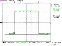
Well, I built a digital pot for my GC as an experiment, and it turned out pretty well. I used a Dallas DS1802 http://pdfserv.maxim-ic.com/arpdf/DS1802.pdf in Stereo mode. Attached is the view of a 1 kHz 1Vpp sine wave at the inputs and outputs of one channel. Ch1 is the output of the pot, Ch2 is the input. I done have a waveform analyzer to measure distortion, just a 500MHz 2Gs/Second scope. It works pretty well so far, and I am using it between my XM Satellite radio and amp.
Nik
Nik
Attachments
If you're looking for an even more high end digital pot, look for BB's PGA2310.
http://focus.ti.com/lit/ds/symlink/pga2310.pdf
http://focus.ti.com/lit/ds/symlink/pga2310.pdf
Elkaid said:If you're looking for an even more high end digital pot, look for BB's PGA2310.
http://focus.ti.com/lit/ds/symlink/pga2310.pdf
Yup. Nice chip.
One nice thing about the Dallas chip is that it doesn't require any sort of digital interface to control it. You can use simple pushbuttons which is a big plus for those who don't want to mess with microcontrollers.
se
Mantram-
Cool. I use an XM SkyFi as my favorite source. I love it. Have a thread with my new headphone amp and skyfi just up tonight:
http://www.diyaudio.com/forums/showthread.php?s=&threadid=18922
How hard was it to incorporate the Digital pot? Did you run another PSU for the 5v?
Could you post a circuit, with PSU included??
Thanks,
GnD
I'm testing the digital pot for inclusion into what I'm calling a "SatAmp", a GC specifically for Satellite radio. It includes a digital pot on the input, and a pair of 3" full range drivers. It will also incorporate either a SkyFi car cradle, or the new Roady Delphi Rx that incorporates the antenna and audio connectors. I'll post a schematic tomorrow, because I left it at work. It is currently powered by an LM7805 off of a 12VDC wall wart, but the circuit will ultimately be powered off of the GC's PSU for simplicity. I'm probably going to be sampling some other digital pots, including the DS1666, which is a single linear taper pot with eeprom to store the wiper settings on power off. I'll use two to eliminate any possible crosstalk. I initially had some hum which was solved by better star-type grounding on the board.GrahamnDodder said:Mantram-
Cool. I use an XM SkyFi as my favorite source. I love it. Have a thread with my new headphone amp and skyfi just up tonight:
http://www.diyaudio.com/forums/showthread.php?s=&threadid=18922
How hard was it to incorporate the Digital pot? Did you run another PSU for the 5v?
Could you post a circuit, with PSU included??
Thanks,
GnD
More tomorrow.
P.S. moderators, would it be possible to get off of moderation and be allowed to include images and edit posts?
BTW here is my current setup, in the absence of my GC, which parts are being gathered for now:
http://www.xmfan.com/viewtopic.php?t=9163
http://www.xmfan.com/viewtopic.php?t=9163
GrahamnDodder said:Did you have to build Wheatstone bridges for each of the channels? And does it knock out the DC offset as it goes thru the chip, or do you have to remove it?
GnD
I didn't use the Wheatsone bridges, and If I had permission to post images, I'd post a screen capture from my scope that shows a 1 kHz square wave at 1vpp on the input and output of the pot. There is about 2-3 mv DC offset on the low side of the square wave, but I haven't done anything about it. I may try some caps on the input to the pot, similar to what is used on the GC's input. The Whaetsone bridges add too much complexity vs. benefits. I like things "simple without sacrificing features".
Schematics tomorrow.
Nik
Digital pot for XM and GC
I am going the whole 9 yards on my XM set up... taking the digital outs into a its own dac and amp. Once I built the digital output, it didn't make any sense to just dump it into a bad dac.
The real killer would be to get a DSP into the mix to be able to play with filters. I tend to think this could be a real winner with the XM signal.
If you are waiting on the Roady, hang on a little bit longer. It will be worth it.
Re: Digital pot for XM and GC
I bought mine exactly 1 week before the press release on the Roady!
No matter, my brother-in-law works for Delphi and gets them for me for $99
Sawzall said:
If you are waiting on the Roady, hang on a little bit longer. It will be worth it.
I bought mine exactly 1 week before the press release on the Roady!
No matter, my brother-in-law works for Delphi and gets them for me for $99
MantramAudio said:moderators, would it be possible to get off of moderation and be allowed to include images and edit posts?
You should be off moderation after a couple more posts, but you can post images, and I don't understand why you say you can't, as you have in your first post on this thread. You have the same editing facilities as all other members, I think it's currently set to allow edits for up to 15 minutes after you post.
")
pinkmouse said:
You should be off moderation after a couple more posts, but you can post images, and I don't understand why you say you can't, as you have in your first post on this thread. You have the same editing facilities as all other members, I think it's currently set to allow edits for up to 15 minutes after you post.
That's weird, last night I never saw the uploaded image. Not even a placeholder. And down at the bottom of each Post Reply form, it shows:
Forum Rules:
You may post new threads
You may post replies
You may post attachments
You may not edit your posts
HTML code is OFF
vB code is ON
Smilies are ON
Yup. Nice chip.
One nice thing about the Dallas chip is that it doesn't require any sort of digital interface to control it. You can use simple pushbuttons which is a big plus for those who don't want to mess with microcontrollers.
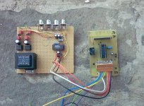
Yes, but you don´t really need much for a simple MC control for PGA2310:
Attachments
till said:
Yes, but you don´t really need much for a simple MC control for PGA2310:
Till, that looks simple enough, you have to use a pic? Or is it possible to control it with “off the shelf parts”?
till said:
Yes, but you don´t really need much for a simple MC control for PGA2310:
Nice
I didn't read the PGA2310's datasheet, but I see 4 RCAs on your board.
Does this chip also do input selection?
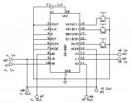
As promised, here's the schematic I'm using right now. I'm not sure how I SHOULD be testing it, but here is what I have done so far:
With the chip powered by +5 single supply, input shorted to ground, output DC offset is .006 mv at the output. This is read with no resister across the output.
Same scenario with a 51 k resister, DC offset is the same.
With a 1Vpp square wave at 1kHz, no attenuation on output, DC offset is 243 mv
Same scenario with full attenuation, DC offset is -68mv
The DC offset also varies widely with the frequency of the sinewave, going lower ast frequency decreases. DC offset of the function generator is < 10mv at 1kHz.
Not sure if this is the right battery of tests or not.
Attachments
- Status
- This old topic is closed. If you want to reopen this topic, contact a moderator using the "Report Post" button.
- Home
- Amplifiers
- Chip Amps
- Digital Pot for GC