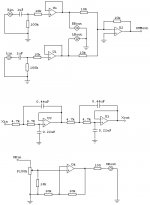
I'm planning to build a DIY subwoofer amp. As the first step, I collected informations on active crossovers from the internet and came up with the following circuit. It consists of four sections: input buffer, mixer, two R-L filters in series, and output buffer with volume control. Because this amplifier will be used with my DVD player, which has only one pair of audio lineout (left and right), it needs to have a pair of buffered outputs which will be connected to my receiver. My reciever doesn't provide any lineout connection. The target crossover frequency is ~100 Hz which is pretty close to the value (109 Hz) from the resistors and capacitors shown in the circuit.
I will make a PCB for this amplifier and would like to make sure that this circuit will work before I print out the PCB layout. So, any recommendation and suggestion will be appreciated. Thanks.
I will make a PCB for this amplifier and would like to make sure that this circuit will work before I print out the PCB layout. So, any recommendation and suggestion will be appreciated. Thanks.
Attachments
I think you mean "RC" not "RL."
In any event, the first thing that strikes me is that you've got the possibility for the opamps to lose their DC ground reference. There's also the potential for some major pops and bangs should some connections get loose.
Tie the buffer input to DC ground with a meg or so resistor. Tie the Xin inputs of the filter blocks to DC ground the same way.
A more global question is what acoustic crossover you're aiming at; it's rare that a desired electronic response will give you what you want acoustically unless you take the speaker's acoustic responses into account. What are you using for an upper-range speaker? Ported or sealed? f3?
SY said:I think you mean "RC" not "RL."
Thanks for the reply. What I meant by "RL" was "Linkwitz-Riley". I should have written "LR" instead of "RL".
")
In any event, the first thing that strikes me is that you've got the possibility for the opamps to lose their DC ground reference. There's also the potential for some major pops and bangs should some connections get loose.
It's hard for me to understand why the opamps could lose their DC ground reference. Could you tell me more about it, please?
Actually, many part of this circuit came from Rod Elliot's website. This circuit is almost the same as the low-pass section in his electronic crossover design except for the summing amplifier which was copied from another project of his. One thing strange is that he didn't mention anything about "DC ground reference" problem. Maybe he's missing something? I thought his design is VERY reliable. Maybe not.... I don't know.
Diode said:Jazz,
Dude, just go buy a cheap receiver that will do Dolby digital. Those have sub outputs. They are pretty cheap these days. I'm not trying to crush your project, just giving another idea..
With respect,
Chris
Thanks for your idea which is exactly the same as my wife's who is not an audiophile and doesn't want to be one either. The main purpose of my projects is just for FUN. "The JOY of building". If I had wanted the answer like yours, I wouldn't have post my message here. No offense to your idea.
JAZZ2250 said:
It's hard for me to understand why the opamps could lose their DC ground reference. Could you tell me more about it, please?
If your Xin is not connected to something with a DC ground reference (a cable not plugged in, for example, or a cable pulled out- these things happen!), the noninverting input of U3 will not have a DC return path.
BTW, I was somewhat unclear about the buffer- when I said to tie its input to ground via a large resistor, I meant at the input jack. That way, the end of the coupling cap isn't floating, a likely source of some nasty bangs.
I'm wondering how much gain I should give to the subwoofer amp.
The input buffer and active crossovers will give a gain of 0, and the output buffer will give a gain of 6dB which can be adjusted by a volume pot. Higher frequencies (higher than the crossover frequency for the subwoofer) will be driven by LM3875 based amplifier with a gain of 27 dB. Of course there will be a volume pot at the inout stages of the LM3875s.
BTW, I'll be using PartsExpress 299-720 DVC subwoofer which can handle upto 50 watts/75 watt max.
Hi Jazz2250,
I made an el-PipeO sub this weekend. For the electronics I used the passive crossover suggested in the article and then connected it to a 25W amp. I have to say that it goes loud but not that loud, so for home theatre you may need some extra power here. I don't know the sensitivity of the driver I used though.
Miguel
miguel2 said:Hi Jazz2250,
I made an el-PipeO sub this weekend. For the electronics I used the passive crossover suggested in the article and then connected it to a 25W amp. I have to say that it goes loud but not that loud, so for home theatre you may need some extra power here. I don't know the sensitivity of the driver I used though.
Miguel
Could you post more details about your project? What kind of driver and amplifier you used? Thanks.
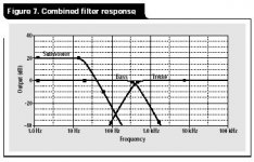
According to the TI application note, +20 dB higher gain is given to the subwoofer section than the higher frequency range. I'm wondering if this is a general rule of thumb? I attached a figure from TI on the following post.
Hi Jazz,
I cannot give you information about the driver because the only things I know is that it has 30 cm diameter and is from Phillips. I had it laying around for years and then I decided to put a sonotube over it and power it. The amp I am using is a Rotel RA921 integrated, again because I had it doing nothing since I finished the ZenV4.
It is not the best performing sub of the world, but it sounds nice when not pused and it cost me something like 10 euros to set it up .
.
Miguel
I cannot give you information about the driver because the only things I know is that it has 30 cm diameter and is from Phillips. I had it laying around for years and then I decided to put a sonotube over it and power it. The amp I am using is a Rotel RA921 integrated, again because I had it doing nothing since I finished the ZenV4.
It is not the best performing sub of the world, but it sounds nice when not pused and it cost me something like 10 euros to set it up
.Miguel
I changed my mind not to use a summing circuit. Instead, I'll run both left and right channels separated to drive DVC subwoofer.
I quickly built the buffer and XO circuits on breadboard and connected it to power op-amps: LM3875, OPA549 and OPA541. XO frequency was ~ 100 Hz. I'm not exactly sure why, but LM3875 showed great distortion. Maybe the chip I used was wrong or LM3875 is not good as a subwoofer amplifier. OPA541 and OPA549 were OK.
Right now, I don't have a subwoofer. So, I can tell nothing about the sonics, but both two chips made pretty good sound when tested with my MTM speaker with two 6.5" woofers.
All the parts are on the way now, so I'll be able to assemble everything in a week or so. Meanwhile, I'll have to make a PCB pattern of +/- 15V power supply and XO circuit on a single PCB.
Banned
Joined 2002
Just a little hint Don't Run A stereo signal into that amp when useing it to power a dvc' sub. I tryed that and at loud volumes well lets just say that the voic coial came apart. left and right channels are not equal one will have a higher peak than the other. I learned the hard way. so if your going to use that amp stereo one. then make sure that the signal is mono either the left or the right into that sub. : O ) Hope this helps. ( hope my info is true. And/Or helpfull. )
JasonL said:I tryed that and at loud volumes well lets just say that the voic coial came apart.
Ouch!!! That's a pain. It's surprising for me that it really happened. Well... Mono or Stereo... That is the problem.
Is there any website showing mechanical drawing of DVC woofers? I want to know how they're made of.
Thanks for the tip, JasonL.
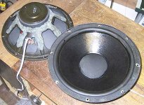
miguel2 said:I cannot give you information about the driver because the only things I know is that it has 30 cm diameter and is from Philips.
Here is a pic of some similar Philips (same but 8 ohm IIRC) drivers i put in an aperiodic push-push sub. They have been puzzle-coated & ductsealed for improved performance.
dave
Attachments
planet10 said:
Here is a pic of some similar Philips (same but 8 ohm IIRC) drivers i put in an aperiodic push-push sub. They have been puzzle-coated & ductsealed for improved performance.
dave
And, you're driving these guys with which subwoofer amp? A DIY or a commercial one? I hope it's a DIY.
JAZZ2250 said:And, you're driving these guys with which subwoofer amp? A DIY or a commercial one? I hope it's a DIY.
A ParaPix 2 x 50 W amp (2xLM3886).
The sub is used in an HT system by a friend with 4 RS40-1197 BD-Pipes.
dave
Finally, I completed DIY subwoofer amplifier on a breadboard. Input section consists of two buffers (L and R) followed by a summing amplifier. Crossover is two Linkwitz-Riley crossovers in series. Output stage is a buffer with a gain of two. Volume control is done at the output buffer stage. All the Op-Amps are TL072s powered by LM317 and 337. Power amplifier is OPA549 and OPA541 with a gain of 20 dB. I still haven't decided which power Op-Amp to use in the final design. Right now, I only have a small subwoofer which came with my PC. So, it's difficult to say anything about the sonics. But, it sounds OK, so far.
Attachments
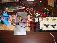
JAZZ2250 said:Finally, I completed DIY subwoofer amplifier on a breadboard. Input section consists of two buffers (L and R) followed by a summing amplifier. Crossover is two Linkwitz-Riley crossovers in series. Output stage is a buffer with a gain of two. Volume control is done at the output buffer stage. All the Op-Amps are TL072s powered by LM317 and 337. Power amplifier is OPA549 and OPA541 with a gain of 20 dB. I still haven't decided which power Op-Amp to use in the final design. Right now, I only have a small subwoofer which came with my PC. So, it's difficult to say anything about the sonics. But, it sounds OK, so far.
do you have a circuit diagram?
Matttcattt said:
do you have a circuit diagram?
Check the first post of this thread for buffers, active XO, and summing circuits. Be ware that the the connection of buffered output is wrong. The center of the phono connector is signal, not ground. My mistake.
You can find the power amp circuit at the following link:
http://home.attbi.com/~greggbaker/invertedLM3875.gif
- Status
- This old topic is closed. If you want to reopen this topic, contact a moderator using the "Report Post" button.
- Home
- Amplifiers
- Solid State
- DIY subwoofer amp