http://www.hostboard.com/cgi-bin/ultimatebb.cgi/ubb/get_topic/f/3729/t/3273
Greets!
Averaged specs used:
Fs' 28.84
Qts' 0.307
Qms' 4.614
Qes' 0.329
Vas' (L) 473.024
Re' 6.442
Le' 1.295
Sd' 856.336
BL' 15.383
Sens' 97.24
Znom' 8
Being fond of the 800 series cab's baffle proportions, an 81" long folded pipe looks good with internal dims of 40.5" H x 28.5" W x 18.75" D including 3/4" divider, so just a hair over the 12 ft^3 limit with external dims of 42" W x 30" W x 20.25" D. Driver down from top front 8.5" and 6" dia. (or other shape = 28.274"^2) x 2" vent on the rear up 17.56" from the bottom for a ~27 Hz Fb.
GM
Attachments
") Nice one Greg.
Nice one Greg.Thanks GM!
The partition would be dividing the box in half width-wise I assume. Is the height of the partition such that the opening between the two halves is the same as the cross sections? With the partition going side to side will two braces front to back be enough?
I'm planning on crossing the 511 at 800Hz, I have an electronic crossover that I can play with to start but at some point I'll do some passives.
I'll post some progress photos as things move along. This close to Xmas, it will have to start in early January. My wife is OK with the cabinets but she wants me to help with shopping. A good trade off for me.
Thanks again for your help and patience, I really appreciate the effort on your part.
Kyle.
Greets!
You're welcome!
I really need to take the time to learn how to draw with a CAD program (sigh).........
Correct.
Correct again, more or less, since an aspect ratio other than 1.0:1.414 won't have the same gap between the internal top and divider baffle edge if the corners don't have appropriately sized angle boards with their voids filled with Portland cement or a similarly massive material. Combined with a heavy driver though, this makes for a very top heavy speaker, so typically I didn't bother to do this, only tacking a big wad of R-19 fiberglass insulation in the top corners to damp out any out-of-BW mids/HF reflections.
Note that the top plate is a high pressure point, so either doubling up its thickness or making it out of a massive material is required for good mechanical efficiency.
Assuming 11-13 lam 19 mm Baltic Birch or Appleply, it's all I'd add, though I'd place it at a golden or acoustic ratio to average out any panel resonances.
Note that supporting/bracing/mass loading the driver is key to best performance, but we'll talk more when you get to that stage.
Anyway, this is just one design, I'm planning to do at least one more, a Weems style Voigt pipe similar to Jay Fisher's stillborn Iconic 704 alignment, so a January start date leaves me plenty of time in theory.
GM

Greets!
Yeah, what we need is one that allows us to freehand sketch it and the program squares it all up except for angles, which we'd have to define somehow, then scale it from inputted dims.
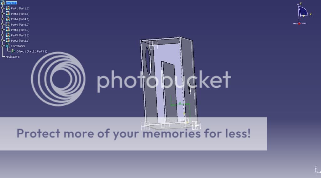
Anyway, when I mentioned adding bracing I didn't mean for you to actually do any until I could define it a bit, though as long as the top back center brace pre-loaded/supported the driver it looks fine, if maybe a bit much if the appropriate plywood is used. Not that you can have too much bracing, just a point of diminishing returns that mostly just reduces net Vb.
GM
Yeah, what we need is one that allows us to freehand sketch it and the program squares it all up except for angles, which we'd have to define somehow, then scale it from inputted dims.
Anyway, when I mentioned adding bracing I didn't mean for you to actually do any until I could define it a bit, though as long as the top back center brace pre-loaded/supported the driver it looks fine, if maybe a bit much if the appropriate plywood is used. Not that you can have too much bracing, just a point of diminishing returns that mostly just reduces net Vb.
GM
Re: 604/704
Well, assuming we're talking about the 704-8A, it wouldn't be my first choice since the driver is a bit low and the net Vb a bit small, though it could be spaced up of course and with more series resistance would have the same response plot. Adding 4" to the height to keep it on the floor and raise the driver up loads the vent a little more, which allows it to be reduced to 1.5" long to get ~the same, yet slightly better damped, response, though I'd be surprised if it was an audible difference in-room.
GM
JimW said:Would this cabinet be a suitable design for the Iconic/GPA 704/604 drivers?
Well, assuming we're talking about the 704-8A, it wouldn't be my first choice since the driver is a bit low and the net Vb a bit small, though it could be spaced up of course and with more series resistance would have the same response plot. Adding 4" to the height to keep it on the floor and raise the driver up loads the vent a little more, which allows it to be reduced to 1.5" long to get ~the same, yet slightly better damped, response, though I'd be surprised if it was an audible difference in-room.
GM
That would be great! Ultimately I want a library of diverse Altec cab designs for folks to choose from similar to what's being done here: http://www.frugal-horn.com/spawn.html
GM
GM
With all the advice and help you've given me recently and in the past I'd be happy to help with drawings, provided you don't need them all at once. I may even start to remember how this stuff works. If I can sort it out, I'll measure and model an 811 and 511 but if I remember correctly, the process is slightly more difficult. I imagine that would be handy at some point.
The link has some nice looking boxes. It would be great to have an equivalent library for full size speakers.
The link has some nice looking boxes. It would be great to have an equivalent library for full size speakers.
zelgall said:With all the advice and help you've given me recently and in the past I'd be happy to help with drawings...........
Got pointed to this old thread today........ any update on the build?
GM
Cambe,
Personally, I would wait until I had the speakers and measured T/S parameters for each before building cabinets. A frequency sweep of Z-impedance is easy to perform and provides good driver A vs. B comparison data.
You could download a room gain simulation program like Jeff Bagby Baffle Edge Diffraction Simulator V 1.2, and study low frequency effects of room/wall placement. You may decide to use a screw-in flare port that simplifies changing the port pipe length.
A couple Google searches for MLTL cabinets will show edge round-overs, bottom ports, side ports, square ports, corner cabinets, etc.... for form vs. function customization.
- Home
- Loudspeakers
- Multi-Way
- MLTL Cabinet for 416-8B