Other pick-up arms have been shown, so I thought I ought to share mine.
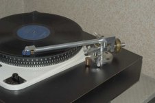
The unipivot is a cup of PTFE bearing on a Biro pen tip. (Lowest possible friction, and it won't rattle).
All adjustments are non-interactive, and can be locked off after adjustment. For initial setting up on a plinth, the arm length is adjustable (by about 5mm) using a screw, and then locked off by the countersunk screw visible on the top of the bearing housing.
The bearing and bias compensation are at stylus height to maximise rocking stability and minimise interaction. The centre of gravity is fractionally below bearing height to maximise the frequency of rocking (which makes it easier to damp).
Damping is different in the three degrees of freedom. Minimum damping up and down, and maximum damping for rotation and rocking.
The headshell was made from a block of 1" square section in order to make a tapered stub to go into the arm tube. My only regret here is that I made it before the Naim Aro, and didn't think to leave a side brace...
I made it because I wanted an SME V, but that cost £1000 (at the time), and I decided that for £1000 I could easily buy a small lathe, build the arm, and still have a lathe afterwards.
The arm tube is wired with fine copper litz wire in two twisted pairs, which is then wired to twisted pair silver in overall screen.
I'm very pleased with it.
PS I've just discovered that I've posted this in the wrong forum. How do I move it?
Attachments
Unipivot vs SME V?
Who knows how it compares to an SME V? But the sound is good enough to have justified the time and expense (I've made lemons too). It's better than my previous unipivot, it's easy to set up, and it's even reasonably tolerant of sideways thumps on the plinth.
Who knows how it compares to an SME V? But the sound is good enough to have justified the time and expense (I've made lemons too). It's better than my previous unipivot, it's easy to set up, and it's even reasonably tolerant of sideways thumps on the plinth.
Re: Drawings
if you can't i can convert that into gis or pdfs so they can be shared.
dave
EC8010 said:No, I don't have drawings, but I could have. The only problem is that they would be in AutoSketch (baby sister to AutoCad) format. I'm quite willing to share, though.
if you can't i can convert that into gis or pdfs so they can be shared.
dave
Re: UNIPIVOT.
Not on this one (it just doesn't seem to need it), but I have on previous arms. Surprisingly, you don't need very much damping at all to tame them. Insulating tape (much lighter) is perfectly effective, and it doesn't even need to cover the entire tube. I found that a single layer ring, then a gap of equal distance, then another ring was quite sufficient.
It's possible that the reason this arm doesn't need damping is that the tube is not abruptly terminated at either end. The headshell stub has a conical hole so that the wall thickness tapers from <0.25mm to 3mm over a distance of about 25mm, and, as you can see, the bearing housing is also tapered.
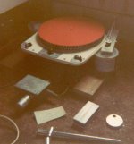
Just for laughs, I've attached a picture of my very first unipivot. Sadly, this was taken by a Kodak Instamatic pointing into the light, without a flash. And if you think the quality is poor, you should have seen what it looked like before I tweaked it. The high-tech Garrard suspension can clearly be seen together with the Acrylic arm board. The honey damping isn't visible. (By the way, honey crystallizes after time.) The cartridge is a Shure M95ED.
The bits of metal lying front of the turntable later became a rather more sophisticated arm. The die-cast aluminium box is a mono valve pre-amplifier with passive RIAA. Lurking at the back is a Quad II.
fdegrove said:
Have you tried heatshrink tubing on the armtube to tame (and lower) it's Q?
Cheers,
Not on this one (it just doesn't seem to need it), but I have on previous arms. Surprisingly, you don't need very much damping at all to tame them. Insulating tape (much lighter) is perfectly effective, and it doesn't even need to cover the entire tube. I found that a single layer ring, then a gap of equal distance, then another ring was quite sufficient.
It's possible that the reason this arm doesn't need damping is that the tube is not abruptly terminated at either end. The headshell stub has a conical hole so that the wall thickness tapers from <0.25mm to 3mm over a distance of about 25mm, and, as you can see, the bearing housing is also tapered.
Just for laughs, I've attached a picture of my very first unipivot. Sadly, this was taken by a Kodak Instamatic pointing into the light, without a flash. And if you think the quality is poor, you should have seen what it looked like before I tweaked it. The high-tech Garrard suspension can clearly be seen together with the Acrylic arm board. The honey damping isn't visible. (By the way, honey crystallizes after time.) The cartridge is a Shure M95ED.
The bits of metal lying front of the turntable later became a rather more sophisticated arm. The die-cast aluminium box is a mono valve pre-amplifier with passive RIAA. Lurking at the back is a Quad II.
Attachments
HONEY?YOU'RE KIDDING.
Hi,
Well,yes.
The better the arm the less damping it requires.
I always found the better unipivots to sound far more dynamic and live sounding.
Currently I use a couple of early Air Tangents which are,in a way, unipivots too.
The reason for the arm not requiring extra damping lies in the fact that a single point of energy drain is a much better defined path than any multiple bearing one.
The point and cup arrangement also makes it hard for any straneous energy to run back to the arm/stylus.
Cheers,
Re: Re: Drawings
It's a deal. I'll see what I can do in the way of drawings. Have you done this file conversion before? If so, what are the pitfalls?
planet10 said:
if you can't i can convert that into gis or pdfs so they can be shared.
dave
It's a deal. I'll see what I can do in the way of drawings. Have you done this file conversion before? If so, what are the pitfalls?
Re: HONEY?YOU'RE KIDDING.
Hmmm, I don't know, but that sounds plausible.
On a good day, it sounds quite a bit like the real thing...
fdegrove said:The better the arm the less damping it requires.
I always found the better unipivots to sound far more dynamic and live sounding.Cheers,
Hmmm, I don't know, but that sounds plausible.
On a good day, it sounds quite a bit like the real thing...
Re: Re: Re: Drawings
Yes. Just ask Variac Actually i used to work doing this sort of thing. Being on a Mac with the right software really helps. The only real issue, i think, are if you use hatches.
dave
EC8010 said:Have you done this file conversion before? If so, what are the pitfalls?
Yes. Just ask Variac
Actually i used to work doing this sort of thing. Being on a Mac with the right software really helps. The only real issue, i think, are if you use hatches.dave
HONEY?YOU'RE KIDDING. No, darling, I'm not.
I fear I may have misinterpreted your post. Were you referring to the honey? If so, no, it wasn't a joke. At the time, suitably viscous liquids were not readily available to an impoverished teenager. But honey was in the kitchen, so it was used. (Could have been worse, could have been black treacle.) It worked really well until one day the arm seized up. The honey had crystallized. Still, hot water and baby buds soon shifted it. After that, I used STP engine oil, but the wires didn't like it, so that spurred development of the posh arm (bits in the foreground). The "posh" arm worked quite well with various Deccas, but was geometrically flawed, and eventually led to the arm at the head of this thread.
Admittedly, honey damping is not one of the more usual Hi-Fi faux pas, but we all make our own mistakes. With hindsight, some are more risible than others.
Well done!
Looks great and has simple and well-considered design. I'm impressed and very interested in details.
What is the arm tube made of? How it is attached to the headshell and to the bearing housing? Didn't quite understand what kind of bearing used? Did you try to dump the tube internally?
Regards and congrats.
Michael
Drawings and materials.
Thank you for the plaudits, chaps.
I didn't do drawings at the time I made the arm, but they can be done now. I will see what I can do. Very little of it requires great precision (that was another design aim).
The arm tube is aluminium (no idea which alloy, it was a piece I had left over from the first large diameter arm). The headshell has a stub that is glued into the tube. I'm afraid I chickened out of making it an interference fit on a stub 25mm long. It could too easily have gone wrong, and then I would have had to make another tube (after cutting the old one away from the stub).
Drawings
Pressure of other work means that it will be a while before I can do the drawings. There are probably rather more than I originally thought because I forgot about the collet that grips the bearing stem and allows arm height to be adjusted. Also, quite a few words will be needed to explain why each bit is as it is, and how to make it in a small workshop Thus, it will be more of an engineering report with diagrams than a set of diagrams on their own.
Pressure of other work means that it will be a while before I can do the drawings. There are probably rather more than I originally thought because I forgot about the collet that grips the bearing stem and allows arm height to be adjusted. Also, quite a few words will be needed to explain why each bit is as it is, and how to make it in a small workshop Thus, it will be more of an engineering report with diagrams than a set of diagrams on their own.
- Status
- This old topic is closed. If you want to reopen this topic, contact a moderator using the "Report Post" button.
- Home
- Source & Line
- Analogue Source
- Unipivot pick-up arm