i completely understand. i really should build a turntable to go with it first (i have some parts, but i'm sure you know how it is") )
)
whenever you get around to it. even just rough sketches are ok, as i had som mods in mind. the bearing system interests me tremendously though.
thanks heaps for contributing your work to the forum.
)whenever you get around to it. even just rough sketches are ok, as i had som mods in mind. the bearing system interests me tremendously though.
thanks heaps for contributing your work to the forum.
Re: We apologise for the delay...
just take your time
EC8010 said:Unfortunately, I have rather a lot of other work to do, so I won't be able to devote the necessary time to doing arm drawings and writing explanations before June (this year). Please bear with me on this, it isn't a tease.
just take your timejesserparker said:where did you get your arm lift? do you know of anywhere you can get them OEM? i'm currently building my own diy unipivot, and that is one thing i would simply like to buy, any ideas?
thanks,
jesse
There are millions of nice old functional arm lifts out there, attached to perfectly crap TT's just begging for you to rescue them and put them to work in a cool diy arm. Lots of the higher end Japanese TT's from the late 70's early 80's come to mind. I really doubt you're going to find one OEM unless you can talk one of the manufacturers into giving you a sample or a spare part, and I wouldn't even know who to direct you to. Alternatively, I'm sure SME will sell you one. At a price.
Arm lift
Jesserparker,
I know exactly what you mean. In some respects, making a cueing device is harder than making the arm! It was given to me, but I believe it was salvaged from a very early Rega.
An alternative, which I'm working on at the moment, is to find a very small motor and gearbox to drive a screw to produce the up and down motion. The advantage of this is that you could add an optical sensor to the arm to give automatic lift-off at the end of the record, or you could add wireless remote control to allow you to cue the arm from your listening position.
Brett,
you are absolutely right. The cheapest way of getting a cueing device is to buy a nasty old turntable and throw everything away but the cueing device. Having once asked the price of a replacement arm tube for an SM3009, I shudder to think what a cueing device would cost. Nevertheless, SME are very helpful...
diy unipivot
greetings
I am new so perusing the earlier offerings I came across your uni ,
must say it really looks brilliant and I would be very interested in drawings and description as I have quite a few bits and pieces of extinct arms around , a small lathe drill press and alu and brass bits and pieces.
They will be putting me out to pasture in the not so distant future and it would be a perfect project to tackle in between the lp hunting and cleaning.
please keep me in mind when ready
regards
Cooking instructions.
Gentlemen, I have a drawing. (It's ages since I did technical drawing, so this is going to be really slow.) Unfortunately, my careful line types to delineate centre lines and hidden lines disappeared in the conversion process...
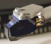
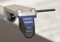
Explanation of what you're looking at: The headshell fits flush onto the end of the 1/2" aluminium arm tube. The tube wants to be reasonably thick (for rigidity) - mine was 1/16" wall thickness. Don't worry about the effective mass of the arm tube, it's the mass at the headshell that's significant.
The headshell is made of a solid block of 25mm (or 1") square aluminium stock - most of which is cut away. The height of the top plate of the headshell above arm tube centre height should be set so that the stylus tip of your chosen cartridge is about 4mm below the arm tube, so that 14mm dimension is not set in stone.
Having cut it roughly to length, face each end in the lathe and align it in a 4-jaw chuck so as to be able to machine the stub that goes into the arm tube in the correct place. Machine the stub diameter so that it requires the arm tube to be lightly bored before it can be inserted. The 11mm dimension is not critical.
Drill the stub to 6mm, and using a really small boring bar, bore the internal taper. the purpose of the taper is to smooth the transition from headshell to arm tube.
Remove and saw off sufficient material to leave an "L" on the end of the stub. Use a mill to form the "L" correctly.
The cartridge mounting slots are formed by drilling four 3mm holes and using a jeweller's saw to join them, then tidying with a needle file. Mark out the hole positions lightly with a scriber so that the construction lines can be removed easily later. The slots are at an angle of 22.5 degrees. The central position of the slots should allow your chosen cartridge to place its stylus tip on the centre line of the arm tube - that's why no dimensions are given.
All of the shapes in the plan view are done by hand - it's easiest.
When the slots are done, the top of the headshell can be rubbed on silicon carbide paper to tidy it up.
The semicircle that joins the arm tube is actually quite easy. Just cut a bit of the tubing you're going to use as the arm tube to about 50mm long, face each end, and bore one end to a reasonably close fit on the stub. Slide the tube on, and file away the headshell material until it is almost flush with the tube. Hold the two parts on 160 grade silicon carbide paper, and remove the last bit. The tube will be scratched but that doesn't matter. When you fit the headshell to the arm tube, it will be perfect.
Finally, drill the hole in the side of the headshell for the finger lift. I used a straight piece of 1/16" silver steel, glued it in place with epoxy, and covered it with heatshrink sleeving to damp the resonance.
Gentlemen, I have a drawing. (It's ages since I did technical drawing, so this is going to be really slow.) Unfortunately, my careful line types to delineate centre lines and hidden lines disappeared in the conversion process...
Explanation of what you're looking at: The headshell fits flush onto the end of the 1/2" aluminium arm tube. The tube wants to be reasonably thick (for rigidity) - mine was 1/16" wall thickness. Don't worry about the effective mass of the arm tube, it's the mass at the headshell that's significant.
The headshell is made of a solid block of 25mm (or 1") square aluminium stock - most of which is cut away. The height of the top plate of the headshell above arm tube centre height should be set so that the stylus tip of your chosen cartridge is about 4mm below the arm tube, so that 14mm dimension is not set in stone.
Having cut it roughly to length, face each end in the lathe and align it in a 4-jaw chuck so as to be able to machine the stub that goes into the arm tube in the correct place. Machine the stub diameter so that it requires the arm tube to be lightly bored before it can be inserted. The 11mm dimension is not critical.
Drill the stub to 6mm, and using a really small boring bar, bore the internal taper. the purpose of the taper is to smooth the transition from headshell to arm tube.
Remove and saw off sufficient material to leave an "L" on the end of the stub. Use a mill to form the "L" correctly.
The cartridge mounting slots are formed by drilling four 3mm holes and using a jeweller's saw to join them, then tidying with a needle file. Mark out the hole positions lightly with a scriber so that the construction lines can be removed easily later. The slots are at an angle of 22.5 degrees. The central position of the slots should allow your chosen cartridge to place its stylus tip on the centre line of the arm tube - that's why no dimensions are given.
All of the shapes in the plan view are done by hand - it's easiest.
When the slots are done, the top of the headshell can be rubbed on silicon carbide paper to tidy it up.
The semicircle that joins the arm tube is actually quite easy. Just cut a bit of the tubing you're going to use as the arm tube to about 50mm long, face each end, and bore one end to a reasonably close fit on the stub. Slide the tube on, and file away the headshell material until it is almost flush with the tube. Hold the two parts on 160 grade silicon carbide paper, and remove the last bit. The tube will be scratched but that doesn't matter. When you fit the headshell to the arm tube, it will be perfect.
Finally, drill the hole in the side of the headshell for the finger lift. I used a straight piece of 1/16" silver steel, glued it in place with epoxy, and covered it with heatshrink sleeving to damp the resonance.
Attachments
 I dunno if my little Lathe will manage(Emco Jewellers Lathe Model ???) , I'll badger a colleague for this part, Ally Steel or Brass ?which is better ?

Swing
Aluminium! Anything else is far too heavy. You really want to make this part. Most arms are let down by their headshell. Detachable headshells are heavy (the plug and socket arrangement) non-rigid (plug and socket, again), and too long (making them less rigid). The headshell should be long enough to clear the cartridge pins from the arm tube, and no longer.
If you are worried about your lathe's swing, the more signficant part is the L-bracket bearing assembly. Have a look at the photograph, and note that you need to be able to bore into a 2" square almost at the edges, requiring about 1 1/2" swing plus clearance for the jaw of the 4-jaw chuck.
- Status
- This old topic is closed. If you want to reopen this topic, contact a moderator using the "Report Post" button.
- Home
- Source & Line
- Analogue Source
- Unipivot pick-up arm