The 2SK2700 looks like a decent candidate
The 2SK2700 was my go to part when I first came up with PowerDrive...about 10 years ago. Sadly it went extinct when the ROHS insanity started. Any of these devices found today are old stock (and should have old dates) or counterfit.
There are dozens of newer and better parts available today to choose from. I, and a few others have used the AOT1N60 from Alpha and Omega semiconductors (50 to 72 cents at Digikey). It is rated for 600 volts and under 2 pF of Crss. I will first try some fets I got at a hamfest for 10 cents each because they have isolated cases. It helps eliminate the temporary loss of vocabulary control caused by touching the metal tab while tweaking the trimpots.
Digging around a little, I found this:.....Looks pretty nice. Just so I understand, the -90V B- rail only needs to be 20-30mA? I assume the 500K pots are to adjust the output tube bias current?
I watched that design unfold a few years ago. It is somewhat similar to the design from the 6L6GC thread except that the first stage is single ended. It will work fine for just about any G1 drive application, but the 12AT7 may not be suitable for some screen drive applications because of the B+ needed to meet the drive voltage requirements.
The B- only feeds current through the mosfets. I like 10 to 20 mA through each mosfet. The schematic that you show runs the mosfet drains at full B+. This can cause instant tube death if a mosfet ever shorts out, by applying B+ to the grid. This is needed if using screen drive, but I usually use a lower voltage for G1 drive amps. Chris designed a regulated supply in the 6L6GC thread, I usually use a FWB on a 230 VCT isolation transformer (N68-X wired backwards) to make +/- 150 volts for the mosfet circuit. This cuts down on the mosfet heat dissipation.
If it were to be done in PPP, would it require four MOSFET source followers to independently adjust the bias points like I do on my PPP UL amps?
Yes, 4 mosfets and 4 coupling caps per channel. Wire the second pair of caps up to the plates of the 12AT7's and duplicate everything up to the OPT's. When building a PPP amp this way, I put in one set of tubes, wire the 8 ohm load to the 4 ohm tap, and get one set to work. Then mark the tubes so you know where to put them back, and remove them. Install the second set and repeat. Then move the load to the correct tap and put in all 4 tubes. Only minor tweaking should be needed for balance.
I'm pretty bent on the 6GF7A as the driver tube.
I have used it, most of its octal relatives (6EM7, 6EA7, 6DN7) and even the small 6EW7's . I find that the small triodes in these tubes have a wide gain variation from tube to tube. This is not a problem if you have a bunch of them and don't mind trying several to get a reasonable gain match. I rememeber building an SE amp that used the 6EM7 as a two stage driver and the gain was very different between the two channels. It turned out to be the 6EM7's. I was able to find a pair where the triodes from each tube matched each other, but I had to try about 10 tubes.
Conventional G1 drive may require 100 volts peak to peak of drive voltage to push a triode wired KT88 or 7403 (search the 6L6GC thread) to full power in AB2. A screen drive amp (or a few other topologies) start at 100 V P-P and go way up. Some tubes may want 400 V P-P of drive. There are bootstraping and positive feedback tricks to get this kind of voltage (McIntosh pioneered this) but I prefer to use a lot of B+ and a tube that can eat it. Tubes designed for use in the vertical output section of a TV set can eat a lot of B+, and are ideal for this application.
The low Mu section of the 6GF7 and its relatives (dual dissimilar triodes for TV vertical sweep duty) are excellent in this respect. The 6GF7A is rated for 1500 volts peak plate voltage.....I don't think we will ever get there! So we have a tube that is designed for TV duty, but relatively unknown in the audio world, but known to be useful. This would be a good candidate in my book, and I do have a little spud amp that uses nothing but a single 6GF7 per channel.
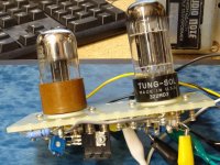
There is however a tube that is revered as one of the best in the audio world, commonly available, but was actually designed for TV vertical sweep use......WHAT!!! Yes the venerable 6SN7 that audio nuts rave about IS a sweep tube. It was used in the vertical section of many black and white TV sets in the 40's. As TV sets got bigger and needed more powerful vertical sweep tubes, bigger dual identical triodes were designed, like the 6BL7 and 6BX7. The 6SN7 carries the same 1500 volt peak plate rating as the 6GF7 while the 6BX7 and 6BL7 are even higher at 2000 volts. I chose the 6SN7 as the driver tube in the 6L6GC design for two reasons. Chris was doing a lot of the testing on this design since I was not always in town to work on it, and he wanted octal tubes, and I was already working on a very similar design that used the 6CG7 which is a 9 pin version of the 6SN7. The design was stated for use as a 6L6GC in AB2 design, but I have used those boards to drive all sorts of tubes including the triode wired 7403's that smiled as they cranked out over 100 WPC in triode. A turret board rendition of this design was tested and used in some of my screen drive experiments (picture 1 below). I haven't explored screen drive with these boards or seen what happens when I apply 650 volts of B+ to them yet......but I will find out soon.
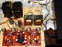
He's the wild man with the Hawaiian shirt that lives down the street from me. His red board is fairly large, hence the "Big red board" title he has another board with just the driver topology on it that is much smaller.
Never met the guy.....in fact never been to Texas other than a layover in DFW, but we have swapped a few emails. His big red board came out at a time when Sherri and I were spending time commuting to rural West Virginia to care for her terminally ill mother, so I had very little Tubelab time. I got one of Pete's big red boards to play with. It kept my interest for about a year and was the only tube amp I played with during that year. I extracted 250 WPC and 525 watts in mono from that board.
I put together a design using the big red board, some $5 tubes, and a couple of $20 Ebay transformers that put out a reliable 125 WPC. I built one and so did about a dozen others. Mine still kicks and has survived several sessions at full volume for multiple hours at a time. I can turn it up, open the windows, and go outside to mow my lawn......without hearing the lawnmower. Nothing in the amp gets overly hot. A picture of the "FlameThrower 250" is included....it has not lived up to its name despite the undersized OPT's that hit saturation causing massive current spikes in the output tubes. Full details of all the experiments are in the big red board thread. Lots of good stuff about sweep tubes in G1 drive too.
Pete's smaller red driver board solves the only problem I have with the big red board......not enough gain. Big red was designed for 18 WPC. It has plenty of gain for that. I get 125 WPC which is nearly 10 db louder, so I need 10 db more gain. Swapping input tubes and plate load resistors gets me a few more db, but I really need another stage. Pete's driver board has that extra stage, and the red boards seen in the picture will be tested in this amp.
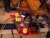
I took one of these boards when I first got it, put 6HB6's in it (a great $1 tube that plugs right into this board) and got 7 watts from the board alone in Class A pentode! (picture enclosed) There are no mosfets for driving screen grids, but I have a mosfet buffer board somewhere.....If I can't find it, I'll make another.
During the last 2 years of Sherri's mothers life I spent a lot of time riding in a car (daily 80 mile trips to Pittsburgh for treatment) or sitting around UPMC hospitals. I designed several PC boards on my laptop. These have been sitting dormant on a flash drive for about 3 years now, but time is becoming available, so it's time to start building some of the stuff that I have been dreaming about for 5 years. The first is the partially populated driver board seen in the picture in my last post. I have no idea if it will work, but I can learn something from it, so it is included for testing against two other known good drivers.
I have had to move all of my "stuff" twice in the past 5 years, and eliminate about 3/4 of it, and there will be at least one more big move coming, so finding parts has been a real challenge, but these baords should be ready for some power this weekend. There are lots more boards still on the flash drive....stay tuned.
Attachments
Last edited:
when looking for optimal mosfet for grid drive, what should be
I don't like mosfets in the signal path in any other service than a source follower, they are just too nonlinear and VVC (voltage variable capacitance)and input capacitance effects are strong.
Things are much simpler in follower configuration.
The input capacitance can range from 100 pF to 5000 pF in a mosfet. This is the capacitance from gate to source. In a common source amp this capacitance must be driven directly by the previous stage. In a follower the source follows the gate. This means that the effective input capacitance is mostly neutralized. It is effectively reduced by 1-the stage voltage gain. Here, having the output accurately track the input reduces capacitance related effects. High Gm is important.
The output capacitance is in parallel with the output in both common source and source follower configuration. This capacitance must be fed by the current flowing through the mosfet. Again, high Gm at the operating current is what's needed.
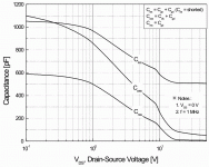
The reverse transfer capacitance is the capacitance from gate to drain. The drain operates at AC ground in a follower, so this capacitance is in parallelwith the input and must be driven by the previous stage. In our applications this is the plate of the driver tube. This is why we want this capacitance low, and relatively constant in the range of voltages the fet will see at full power output. This is the voltage across the fet as it is driven through its entire signal swing. It become obvious that the higher the drive requirements are, the greater the voltage swing across the fet are. We want to keep the minimum voltage across fet above the point where the Crss begins to increase. About 20 to 100 volts with most fets.
So we are looking for a fet with a low but constant Crss in the voltage range where it will be used. A high Gm is needed, but this is usually the case with most fets, and why many tubes fall short as cathode followers. Of course the voltage, power, and current requirements must be satisfied. If the amp will see repeated clipping, like a guitar amp, allow ample(2 to 3X) headroom for these ratings...especially voltage. Avoid excessively large fets because their Gm may drop at low currents, and the capacitance may be high.
The more I read your posts George, the more I talk myself back into straight pentode mode with no screen drive.
Screen drive has its benefits and its drawbacks. The biggest benefit is higher efficiency and lower idle current. This can be an advantage if higher power output for a given tube set, or lower heat output, are needed or wanted in a particular design. An added benefit of lower heat output is longer tube and component life.
The drawbacks are much higher drive requirements, and the ablity to blow the screen grid into next week under strong overdrive. The drive requirements can be overcome, and the grid melting thing can be eliminated if the driver clips before the meltdown region is reached. Sometimes this is as simple as a resistor or a CCS chip in series with the positive supply to the driver fet.
The choice is obviously up to you. I don't mind blowing things up, and I aim to learn more about screen drive VS G1 drive VS both at the same time!
If you want 75 to 100 WPC and you didn't have your OPT's already, I would say it's a no brainer.....Pete's big red board on 650 volts with 6HJ5's and a 3300 ohm load. 125 WPC and excellent reliability. The same thing could be built with Pete's little red and just about any 25 watt sweep tube. Your OPT's and 4X 6CB5's will work, but I think the B+ will fall in between 450 and 550 volts to get 75 to 100 WPC. I am sure that load lines could be plotted and all this figured out, but for me it's easier and far more fun to just wire it all up and turn the power supply knob up till it glows or blows!
Hopefully this will come soon.
here is a good read....An Audio Amplifier Design Philosophy
I read about David Berning's exploits on his web site years ago. Like him I got started with tubes at a very young age for the same reason....they were free by the bag fulls where ever old TV's, radios, and stereos were discarded. Unlike him, I didn't follow my dream to invent stuff, I got a job at a major electronics company over 40 years ago where I still work. I must state that David claims to have invented screen drive, and patented it, but screen drive (and G1 + G2) circuits can be found that date back to WWII and before. The ZOTL circuit is however, pure genius. My attempts to copy it have only resulted in many blown mosfets.
hey George,
i must say i admire your patience in typing out replies...
i have begun to hoard power sweep tubes i intend to use on Berning's..
a local store has begun to display their sweep tubes again on their shelves
and at a fraction of the cost in your side of the pond....
is U$9 good for a 6HF5, or 6KD6, or 6LW6?
tubes are still in boxes that looked fresh....
wrt mosfets, i found the following available in our local shops...
IRFBC20, IRF820, FS3KM-16A, FS3KM-18A,FS5UM-14A, the last 3 are Mitsubishi devices and have built in gate protection zeners...
I'm a lot like you with all tube circuits. I build and tweak from there taking measurements, blowing tubes, and learning.
The sand is something I have never used. I can see the benefits based on what I've read about screen drive. It looks like fun to try. As of now, I've got eight 6CB5s, a pair of 1.9K 120W outputs, and a fist full of driver tubes. I will drop by my surplus shop tomorrow and take a gander.
They always have fets that are extinct, and they are cheap.
I'd like to see around 100W from 4 6CB5A tubes. Pentode with a classic front end or screen drive.
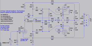
I was playin' sims with an equal Z concertina and deblocker in AB2.
everything seems cool in G1 drive (to +20V AB2), so lets go crazy!
Just took a lame stab to see what would happen if we re-bias Vocm
for screen drive. 90Vocm gives about 40mA quiescent per Tetrode.
Meaning of Vocm explained: Fully Differential Op Amps Made Easy
http://www.ti.com.cn/cn/lit/an/sloa099/sloa099.pdf
In G2 drive: Looks like Concertina runs out of headroom before the
output reaches full swing. Just not gonna work without more Volts.
I mean, it works fine, just half the output swing I had before in G1.
In G1=G2 drive: Volt headroom isn't the problem. Concertina runs
shy of current to drive the grids and work against the de-blocker to
re-charge caps in the cutoff half-cycle. Q1 already stressed above
limits in this drawing. 67mA concertina quiescent is not enough.
I tried offsetting G2 some volts above G1, but still not found any
configuration thats reasonable for a de-blocked concertina drive
except G1 AB2 UL , what I stated with...
Maybe someone else can figure a better use for these new ideas?
Attachments
Last edited:
the last 3 are Mitsubishi devices and have built in gate protection zeners...
I forgot to mention this last night. The fet must have a protection zener, or you must add one externally. A single zener that will clamp the gate at a voltage above the source that is well above the 5 to 10 volts needed for normal operation but below the maximum gate - source breakdown voltage, usually 25 to 30 volts, is all that is needed. The gate shouldn't need to operate below the source, but it can go there on power up and hard clipping, instantly blowing the fet.....I have several dead ones to prove this.
Forum problems limit my postings for now....page not found......
I was playin' sims
I tried simulating screen drive several years ago with limited results. I can tell you that a 6L6 type is not the tube to use, in simulation or real live circuits, the screen grid isn't sensitive enough. There was a model for a sweep tube that I found on the web somewhere that worked better.
This is a sim for an augmented cathode follower from 2007 try the 6KG6 model.
I tried wiring the two grids together like this in real life and I got exploded fets. I had some success in the old G1=G2 thread (a working 40 watt amp) with resistive dividers, so I plan to start there, or even use two mosfets, one for each grid.
Tony, I haven't forgotten those 4d32's
Attachments
If I use one power transformer for B+ 680V and filaments, and another for a choke input supply to feed the grids, does it still need to be regulated? The screens would stay pretty constant despite plate current.
With 680V B+ and 150V on the screens. I can tap the half way point of the doubler for the driver tube B+ of 340V or so.
With 680V B+ and 150V on the screens. I can tap the half way point of the doubler for the driver tube B+ of 340V or so.
In theory the screens need to be regulated to provide the lowest distortion. In order for the tube current to remain constant with variations in power line voltage, the control grid should also be regulated. In most cases the main plate supply does not need regulation if there is enough capacitance to avoid big sags on bass transients.
My 125WPC version of Pete's big red board uses two power transformers with seperate rectifiers that each provide about 325 volts. These two supplies are wired in series. The bottom transformer feeds the unmodified board (except that the diodes are 1000 PIV 3 Amp) which rectifies the AC, filters and regulates the screen with a zener stabilized source follower. The bias supply is unregulated, and the driver supply uses a capacitance multiplier filter.
The second transformer uses a bridge rectifier and a 470 uF 400 volt electrolytic and a 1.5 uF film cap as the only filter. This supply is wired in series with the on board supply to provide plate voltage for the output tubes only. The idle voltage is about 650 volts and at 250 watts total output (sine wave at the onset of clipping) it is about 620 volts.
This arangement works, but is not ideal. When the line voltaage drops the tube current goes up because the unregulated bias supply drops. I will use a zener - mosfet regulated supply in the next amp. The details on the construction of this amp is somewhere in Pete's big red board thread. I know of at least 5 builders that copied it, and Pete reported an increase in board sales after it was posted.
Pretty much the same thing I just described.
My 125WPC version of Pete's big red board uses two power transformers with seperate rectifiers that each provide about 325 volts. These two supplies are wired in series. The bottom transformer feeds the unmodified board (except that the diodes are 1000 PIV 3 Amp) which rectifies the AC, filters and regulates the screen with a zener stabilized source follower. The bias supply is unregulated, and the driver supply uses a capacitance multiplier filter.
The second transformer uses a bridge rectifier and a 470 uF 400 volt electrolytic and a 1.5 uF film cap as the only filter. This supply is wired in series with the on board supply to provide plate voltage for the output tubes only. The idle voltage is about 650 volts and at 250 watts total output (sine wave at the onset of clipping) it is about 620 volts.
This arangement works, but is not ideal. When the line voltaage drops the tube current goes up because the unregulated bias supply drops. I will use a zener - mosfet regulated supply in the next amp. The details on the construction of this amp is somewhere in Pete's big red board thread. I know of at least 5 builders that copied it, and Pete reported an increase in board sales after it was posted.
I can tap the half way point of the doubler for the driver tube B+ of 340V or so.
Pretty much the same thing I just described.
OK,
Will string Zener work for both bias supply and SG regulation?
I assume you would regulate the bias supply at 10-20% over the max negative bias and use a pot like a standard bias adjustment circuit?
What kind of negative bias voltage is necessary for sweeps? Do they need more current on the negative supply?
yes an external zener helps if not using a mosfet with built in zeners....
and yes, a bias pot to control mosfet current will be handy....
g1 is biased at 0 volts, g2 is biased so that cathode current is about 3 to 5mA,
the mosfet drain current is the one that is not so clear to me, i suppose that depending on your heatsink, Vdd and -Vss. in any case, the device power dissipation limits current imho...
since it is the positive swing that is important, i would say about 150 volts Vdd is good....
tubelab will correct me if i am wrong......
You need to keep the Mosfet current above a certain threshold depending on type due to the gate capacitance stuff. I have found that generally above 10mA is good for most types. So that's 40ma for 4 tubes. So the negative supply does need to be a bit beefier than your average but 40 or 80ma really isn't too much of a burden.
Cheers
Matt.
Cheers
Matt.
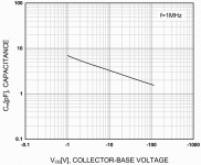
Got nothing whatsoever to do with current.
About leaving 20V on the drain at all times.
2pF Miller shoots up to 600pF over last 20V!
That and no need for gate protecion is why I
chose the "inferior" BJT in the second clip.
If I was assured of 20V to spare, I probably
woulda gone with the MOSFET and a zenier...
About leaving 20V on the drain at all times.
2pF Miller shoots up to 600pF over last 20V!
That and no need for gate protecion is why I
chose the "inferior" BJT in the second clip.
If I was assured of 20V to spare, I probably
woulda gone with the MOSFET and a zenier...
Attachments
Last edited:
OK, I am assuming that deicide67 is now talking about conventional G1 drive since that appears to be his current choice of design.
AJT is referring to screen drive, and all his comments are generally valid with a few exceptions:
If using a mosfet to drive a tube grid directly (either grid) a zener from gate to source is required. Many fets have them built in. The gate - source voltage rating may be violated without this protection during warm up.
The typical bias pot is connected to the gate of the fet, while the source of the fet is connected directly to G1 or G2 (or some combination of grids) of the tube to be driven. The bias pot sets the fets gate voltage, which controls the source voltage in a follower, which IS the tubes grid voltage, thus setting the tubes idle current. This is true regardless of which grid or grids are being controlled.
The mosfet current is set by the resistor connecting the source of the mosfet to the negative supply voltage. Despite one of my early screen drive circuit diagrams that I posted that does not have a resistor, a resistor should be used to set the minimum mosfet current, however the minimum mosfet current requirement has nothing to do with capacitance effects.
Many if not all mosfets and vacuum tubes lose transconductance at low currents. High transconductance is the main reason for choosing a pentode over a triode, and a mosfet over a tube for follower duty.
I have discovered another reason. Mosfets do unexpected things when transitioning through cutoff. The most common ugly thing is a quick burst of high frequency oscillation often well into the HF or VHF region of the RF spectrum. I have seen an amplifier that plays very well, sounds good, and measures good, but blanks out a TV set in the same room! Forcing a minimum current, even when the tube it is driving is cutoff is a good thing. Ferrite beads and stopper resistors are your friends.
Note that some purists will replace this resistor with a CCS to keep the fet current constant. This keeps the Gm constant which in theory is good, but I can hear no sonic benefit, so I don't do this, but you may feel otherwise. Remember that a CCS is just a specially doped high Gm fet that will oscillate if given half a chance. Tying two high Gm fets to the grid of a high GM tube is asking for a TV jammer!
Yes, the maximum current is limited by the size of the heat sink, and higher current may be of some value. Each case is different, depending on the grid current being drawn by the tube. I have 4 really BIG fets mounted to a really big heat sink to explore this area.....and to test them as output devices.
The positive supply voltage on the fet should be 20 to 50 volts above the expected maximum voltage needed by the grid being driven. A conventional G1 driven amp can probably work OK with 50 volts or so, but I typically use a +/- 150 volt supply for the fet since this is easy to make from a cheap isolation transformer, unless some other source is available in the amp, OR the tube requires more positive G1 voltage, like some transmitting tubes.
Some screen drive amps may work OK on a 150 volt mosfet supply, but many require more voltage. You want enough voltage to fully saturate the tube, plus the headroom in the fet. Some tubes need more than 150 volts to saturate them, especially if a slight negative G1 voltage is applied to lower distortion. The 6AV5 needs quite a bit more voltage. I think I needed 300 or more volts in my screen drive experiments with those.
Well, technially not Miller, since there is no voltage gain, but the input capacitance can go wild and more important CHANGES with applied voltage, if there is not enough voltage across the fet. This is one of the main arguments in the SS VS tubes debate (PIM caused by VVC effects) but do you know that a tube exhibits the same (albeit much weaker) effect due to the varying size of the space charge cloud with applied negative grid voltage?
A BJT does work, and I have used them. In some circuits they MAY appear to sound better....but second breakdown and SOA requirements cause them to rapidly turn back to sand when the Big Dumb Blonde One plugs in his guitar and cuts loose. When the BJT or mosfet shorts, the collector (drain) supply gets connected directly to the grid of your tube, and...it really doesn't like this!
Which, reminds me.....put a fuse or a small sacrificial resistor in series with the cathode...or at least the B+ lead of the OPT. Beware the typical glass fuse explodes violently on 650 volts into a shorted cap!
A zener and resistor, or a VR tube and resistor is sufficient for bias supply regulation, and SG supply regulation in small tubes like the driver. The screen current in an output tube can vary over a rather large range, which may be too much for a simple resistor - zener string to handle. A mosfet follower on the zener string can fix this. For an excellent example, copy the screen regulator from Pete's big red board.
If you use a conventional G1 drive circuit (no mosfet) the voltage and current requirements are similar to any other big output tube. The voltage required to fully cut off any given tube can be determined from the curves, and the bias supply should be able to achieve this voltage. The curves for a 6CB5 show cutoff reached at about -50 volts for a G2 voltage of 150 volts. Curves for other G2 voltages are not given, but cutoff will require more negative voltage for a higher screen voltage.
If a mosfet (or cathode follower for tube purists) is used to drive G1 then the current required for each mosfet is added to the negative bias supply requirements, AND to whatever positive supply feeds the drains of the mosfets.
Horizontal sweep tubes have a few advantages over the typical audio output tube:
The screen voltage requirement is low. This may be a disadvantage to some, because it rules out UL and usually triode, and often requires an additional power supply. If the plate voltage is considerably higher than the screen voltage (usually the case) the screen current is low, often under 10 mA. This is what allows screen drive.
The peak current capability is much higher. This makes for unmatched transient handling. It's easy to figure this out. Compare the size of the cathode in any sweep tube to the cathode in a 6L6GC. Which one do you want kicking your woofer around?
A sweep tube can usually be fully saturated without driving G1 positive. Have you ever heard of a sweep tube amp running class AB2? I have found no need to do so. Given proper choices of operating points you can get plenty of power without going into positive G1 territory. This means that mosfet drive is usually not needed.
WHAT???....Yes I have always been a big proponent of mosfet drive, I even call is PowerDrive and use it for most everything I build, but after spending almost 2 years annoying my neighbors with one of Pete's big red boards, and even playing my guitar through it, I have never heard it display any overload recovery effects often heard when overdriving a typical cap coupled audio amp. Note, this may be due to the fact that it has way more power than I need......SO...
I have set up my breadboard so that I can explore the effects of mosfet drive VS conventional RC coupling to the output tubes by swapping out the driver boards leaving the rest of the amp the same. I have a pair of Pete's driver boards set up so that they can deliver 7 watts of power if connected directly to an OPT. That is plenty of drive, it's just RC coupled. They will be compared against other driver boards, and maybe even the same driver boards with an external mosfet board if time permits.
Given that deicide67 probably doesn't want to wait until all these experiments are done to start building, what does he build?????? Well with 600+ volts, 8 X 6CB5's and some 1.9K OPT's, that combination should be capable of say 1.21 Giggowatts of power. A simple G1 driven circuit without mosfets should have no problem driving it to well beyond the OPT's capability, why build more? That's just my first guess though.
I should have some time to play this weekend...still to soon to know how much yet though, but I may be able to fire up something......its been far too long since I fried any parts!!!!!
AJT is referring to screen drive, and all his comments are generally valid with a few exceptions:
If using a mosfet to drive a tube grid directly (either grid) a zener from gate to source is required. Many fets have them built in. The gate - source voltage rating may be violated without this protection during warm up.
The typical bias pot is connected to the gate of the fet, while the source of the fet is connected directly to G1 or G2 (or some combination of grids) of the tube to be driven. The bias pot sets the fets gate voltage, which controls the source voltage in a follower, which IS the tubes grid voltage, thus setting the tubes idle current. This is true regardless of which grid or grids are being controlled.
The mosfet current is set by the resistor connecting the source of the mosfet to the negative supply voltage. Despite one of my early screen drive circuit diagrams that I posted that does not have a resistor, a resistor should be used to set the minimum mosfet current, however the minimum mosfet current requirement has nothing to do with capacitance effects.
Many if not all mosfets and vacuum tubes lose transconductance at low currents. High transconductance is the main reason for choosing a pentode over a triode, and a mosfet over a tube for follower duty.
I have discovered another reason. Mosfets do unexpected things when transitioning through cutoff. The most common ugly thing is a quick burst of high frequency oscillation often well into the HF or VHF region of the RF spectrum. I have seen an amplifier that plays very well, sounds good, and measures good, but blanks out a TV set in the same room! Forcing a minimum current, even when the tube it is driving is cutoff is a good thing. Ferrite beads and stopper resistors are your friends.
Note that some purists will replace this resistor with a CCS to keep the fet current constant. This keeps the Gm constant which in theory is good, but I can hear no sonic benefit, so I don't do this, but you may feel otherwise. Remember that a CCS is just a specially doped high Gm fet that will oscillate if given half a chance. Tying two high Gm fets to the grid of a high GM tube is asking for a TV jammer!
Yes, the maximum current is limited by the size of the heat sink, and higher current may be of some value. Each case is different, depending on the grid current being drawn by the tube. I have 4 really BIG fets mounted to a really big heat sink to explore this area.....and to test them as output devices.
The positive supply voltage on the fet should be 20 to 50 volts above the expected maximum voltage needed by the grid being driven. A conventional G1 driven amp can probably work OK with 50 volts or so, but I typically use a +/- 150 volt supply for the fet since this is easy to make from a cheap isolation transformer, unless some other source is available in the amp, OR the tube requires more positive G1 voltage, like some transmitting tubes.
Some screen drive amps may work OK on a 150 volt mosfet supply, but many require more voltage. You want enough voltage to fully saturate the tube, plus the headroom in the fet. Some tubes need more than 150 volts to saturate them, especially if a slight negative G1 voltage is applied to lower distortion. The 6AV5 needs quite a bit more voltage. I think I needed 300 or more volts in my screen drive experiments with those.
Miller shoots up to 600pF
Well, technially not Miller, since there is no voltage gain, but the input capacitance can go wild and more important CHANGES with applied voltage, if there is not enough voltage across the fet. This is one of the main arguments in the SS VS tubes debate (PIM caused by VVC effects) but do you know that a tube exhibits the same (albeit much weaker) effect due to the varying size of the space charge cloud with applied negative grid voltage?
I chose the "inferior" BJT in the second clip.
A BJT does work, and I have used them. In some circuits they MAY appear to sound better....but second breakdown and SOA requirements cause them to rapidly turn back to sand when the Big Dumb Blonde One plugs in his guitar and cuts loose. When the BJT or mosfet shorts, the collector (drain) supply gets connected directly to the grid of your tube, and...it really doesn't like this!
Which, reminds me.....put a fuse or a small sacrificial resistor in series with the cathode...or at least the B+ lead of the OPT. Beware the typical glass fuse explodes violently on 650 volts into a shorted cap!
Will string Zener work for both bias supply and SG regulation?
A zener and resistor, or a VR tube and resistor is sufficient for bias supply regulation, and SG supply regulation in small tubes like the driver. The screen current in an output tube can vary over a rather large range, which may be too much for a simple resistor - zener string to handle. A mosfet follower on the zener string can fix this. For an excellent example, copy the screen regulator from Pete's big red board.
I assume you would regulate the bias supply at 10-20% over the max negative bias and use a pot like a standard bias adjustment circuit?.....Do they need more current on the negative supply?
If you use a conventional G1 drive circuit (no mosfet) the voltage and current requirements are similar to any other big output tube. The voltage required to fully cut off any given tube can be determined from the curves, and the bias supply should be able to achieve this voltage. The curves for a 6CB5 show cutoff reached at about -50 volts for a G2 voltage of 150 volts. Curves for other G2 voltages are not given, but cutoff will require more negative voltage for a higher screen voltage.
If a mosfet (or cathode follower for tube purists) is used to drive G1 then the current required for each mosfet is added to the negative bias supply requirements, AND to whatever positive supply feeds the drains of the mosfets.
Horizontal sweep tubes have a few advantages over the typical audio output tube:
The screen voltage requirement is low. This may be a disadvantage to some, because it rules out UL and usually triode, and often requires an additional power supply. If the plate voltage is considerably higher than the screen voltage (usually the case) the screen current is low, often under 10 mA. This is what allows screen drive.
The peak current capability is much higher. This makes for unmatched transient handling. It's easy to figure this out. Compare the size of the cathode in any sweep tube to the cathode in a 6L6GC. Which one do you want kicking your woofer around?
A sweep tube can usually be fully saturated without driving G1 positive. Have you ever heard of a sweep tube amp running class AB2? I have found no need to do so. Given proper choices of operating points you can get plenty of power without going into positive G1 territory. This means that mosfet drive is usually not needed.
WHAT???....Yes I have always been a big proponent of mosfet drive, I even call is PowerDrive and use it for most everything I build, but after spending almost 2 years annoying my neighbors with one of Pete's big red boards, and even playing my guitar through it, I have never heard it display any overload recovery effects often heard when overdriving a typical cap coupled audio amp. Note, this may be due to the fact that it has way more power than I need......SO...
I have set up my breadboard so that I can explore the effects of mosfet drive VS conventional RC coupling to the output tubes by swapping out the driver boards leaving the rest of the amp the same. I have a pair of Pete's driver boards set up so that they can deliver 7 watts of power if connected directly to an OPT. That is plenty of drive, it's just RC coupled. They will be compared against other driver boards, and maybe even the same driver boards with an external mosfet board if time permits.
Given that deicide67 probably doesn't want to wait until all these experiments are done to start building, what does he build?????? Well with 600+ volts, 8 X 6CB5's and some 1.9K OPT's, that combination should be capable of say 1.21 Giggowatts of power. A simple G1 driven circuit without mosfets should have no problem driving it to well beyond the OPT's capability, why build more? That's just my first guess though.
I should have some time to play this weekend...still to soon to know how much yet though, but I may be able to fire up something......its been far too long since I fried any parts!!!!!
A BJT does work, and I have used them. In some circuits they MAY appear to sound better....but second breakdown and SOA requirements cause them to rapidly turn back to sand when the Big Dumb Blonde One plugs in his guitar and cuts loose. When the BJT or mosfet shorts, the collector (drain) supply gets connected directly to the grid of your tube, and...it really doesn't like this!
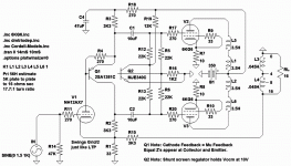
Either BJT could breakdown and would not short the supply to any grid.
Even if shunt regulator Q2 fails open collector: Resistors limit screen to
35V@5.2mA=0.18W. Each 6KG6 plate dissipates 65W in this failure
mode, and even less (about 44W) if there is a music signal present.
Attachments
- Home
- Amplifiers
- Tubes / Valves
- Show me your screen drive circuits