Yap 2.1
Details here.
Details here.
An externally hosted image should be here but it was not working when we last tested it.

Sounds like someone has been sniffing Bobby Carver's underwear again.
Try the search button for fossil schematics, dude.
Try the search button for fossil schematics, dude.
Hi Guys
Here is my latest amp module hot off the press. 🙂
A variant of my nxV200 with the power MOSFETs mounted underneath the main PCB and some improvements to the main circuitry.
Here is my latest amp module hot off the press. 🙂
An externally hosted image should be here but it was not working when we last tested it.
An externally hosted image should be here but it was not working when we last tested it.
A variant of my nxV200 with the power MOSFETs mounted underneath the main PCB and some improvements to the main circuitry.
Wavebourn said:Testing it now, on the picture. All LEDs are bright that means heavy compression, but the sound is still CLEAN! I AM YELLING IN MICROPHONE ARRAY! YAHOOO!!! No clipping at all, but sensitivity is great on 3 feet distance!
What is interesting, a stereobase is wider than in reality. Sensitivity of rear capsules need to be adjusted.
http://wavebourn.com/forum/download.php?id=134&f=7
If you want to hear this microphone through my tube amps and my line array speakers, here is the file from Russian bard festival where I am singing. The record was made by camera so everything is heard, including power generator in the forest. Sometimes when I yell aloud you can see LEDs flashing (in front of the red box on the stage) that means an optical compressor is compressing wildly to avoid clipping.
WARNING! The file is 60 megabytes in size!
http://wavebourn.com/music/alisovski...stival2009.mpg
FastEddy said:
.......................................................................................................
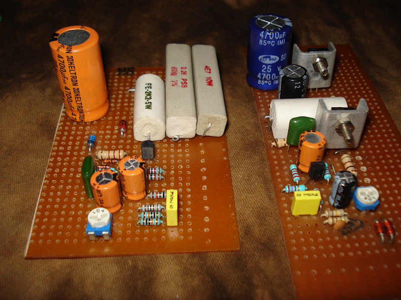
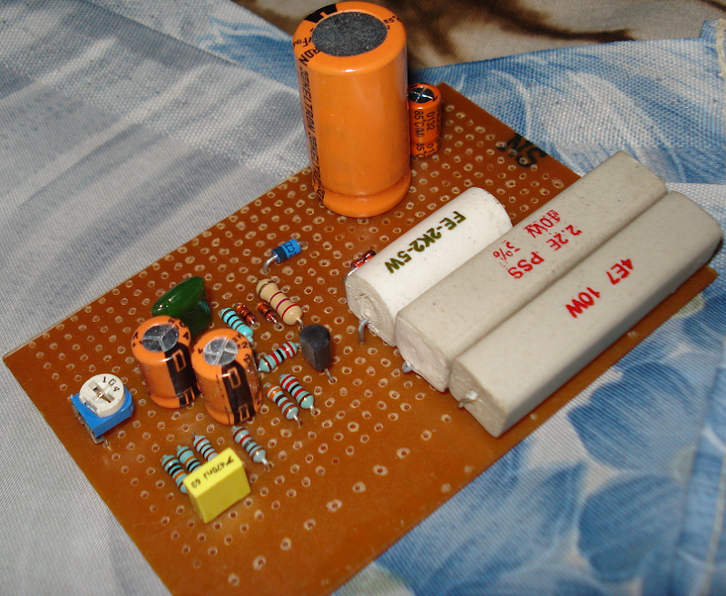
The circuit on the left has the death of zen preamp and all of the Pavel Macura's MOSFET power follower EXCEPT the MOSFET and the NPN Darlington. You can see the 18volt(blue) and 3.3volt(orange) zenners which are parts of the power follower.
I'm gonna drive this from a 50V supply and unfortunately the retailer didnt have a 1.5ohm/10watt resistor so I chose a 2.2ohm and a 4.7ohm resistor in parallel(resulting in a resistance of about 1.49ohm) 😎
The follower is direct driven by the preamp through a 270ohm resistor(the 1watt resistor near the blue zenner), so i think it is direct coupled.

The BIG orange capacitor is the output coupler and is in parallel with a 10uF thing behind it.
I used the polyester(green) capacitor in supply only.
..............................................................................................
/shaan hates everything in the signal path, even a resistor.
The Saint said:Hi Guys
Here is my latest amp module hot off the press. 🙂
Looks neat
Do you know you can make a thread with your amps in "Vendors Bazar"
Would be much better place for posting your company news
tinitus said:
Looks neat
Do you know you can make a thread with your amps in "Vendors Bazar"
Would be much better place for posting your company news
LOLz
"Do you know you can make a thread with your amps in "Vendors Bazar" ..."
Good idea! Do that too!
For myself, I like to see the latest prototypes, where ever, when ever, which ever thread, even if they may eventually end up in production. ... Especially if they might end up in production!
The Saint's work is always of great interest. In this case, did you notice that the power output MOSFETs are on the bottom of the board? ... Using the board itself as a part of the heat sink? ... Fascinating! ... and a testament to alternative thinking, originality = how does he do that? Must be a real thermally efficient design, fur sure.
It looks like the MOSFETs could or would also be mounted using the board through holes to a (heat sink) plate. That's also a nice tight, space saving trick ... good mechanics, worthy of examination by any serious DIY type, here and elsewhere.
Good idea! Do that too!
For myself, I like to see the latest prototypes, where ever, when ever, which ever thread, even if they may eventually end up in production. ... Especially if they might end up in production!
The Saint's work is always of great interest. In this case, did you notice that the power output MOSFETs are on the bottom of the board? ... Using the board itself as a part of the heat sink? ... Fascinating! ... and a testament to alternative thinking, originality = how does he do that?
Must be a real thermally efficient design, fur sure.It looks like the MOSFETs could or would also be mounted using the board through holes to a (heat sink) plate. That's also a nice tight, space saving trick ... good mechanics, worthy of examination by any serious DIY type, here and elsewhere.
Hi Eddy
The MOSFETs are mounted about 3-5mm off the PCB so the PCB doesn't get very warm. its a fairly low power design so the thermal
issues aren't really issues with this design.🙂
The MOSFETs are mounted about 3-5mm off the PCB so the PCB doesn't get very warm. its a fairly low power design so the thermal
issues aren't really issues with this design.🙂
" its a fairly low power design so the thermal issues aren't really issues with this design ..."
Compared to what? The "Death of Zen" above? ... 😱
I know, I know = the purpose of the whole "Death of Zen" concept is absolute attention to best distortion & best quality, not necessarily power or thermal considerations ... but ...
Compared to what? The "Death of Zen" above? ... 😱
I know, I know = the purpose of the whole "Death of Zen" concept is absolute attention to best distortion & best quality, not necessarily power or thermal considerations ... but ...
Just finished my first discrete solid state amplifier (a pair of monoblocks). They're pretty basic, with a paralleled TIP2955 / TIP3055 output stage. The hardest bit about designing the amp was fitting everything into the compact case, but it worked in the end.
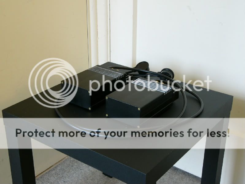
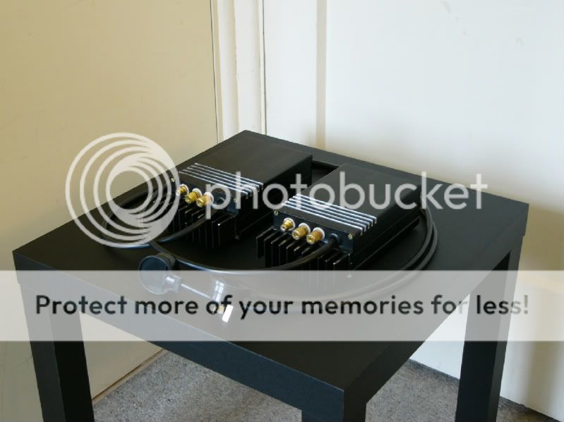
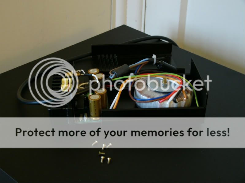
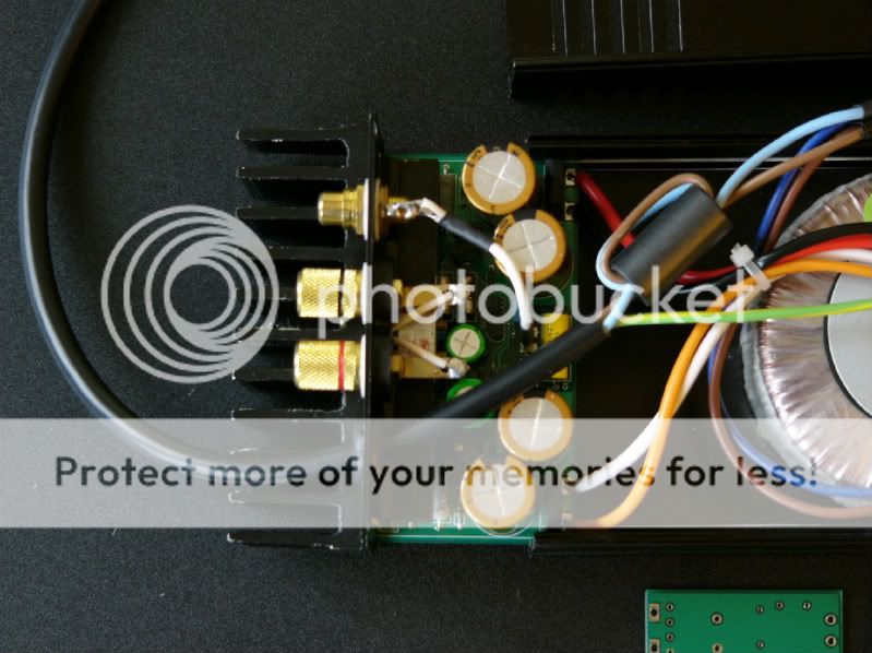
The heatsink / PCB assembly slides out to allow biasing, measuring servicing etc., pictures three and four show this. The PCBs are my own design, made specifically to fit the case.
The heatsink / PCB assembly slides out to allow biasing, measuring servicing etc., pictures three and four show this. The PCBs are my own design, made specifically to fit the case.
My 12 cents:
An externally hosted image should be here but it was not working when we last tested it.
My 12 cents:
An externally hosted image should be here but it was not working when we last tested it.
Nice going Pavel.
A good trick to make the edges meet nicely, is to make a chamfer of 1mm. This way the edges looks like they're lining up perfect, even if you have a slight misalignment.
Magura 🙂
- Home
- Amplifiers
- Solid State
- Post your Solid State pics here