OK I'm starting this thread to dump stuff in with regard to my new MTM project I'm working on. Prompted because I was discussing something with kelticwizard and pretty much starting to thread jack.
Keltic, here is the nearfield measurement of one of the woofers (with both being driven)
I was expecting from the sim, that freq response would start to drop off at 200Hz and the -3db to be about 80Hz, but it's doing the opposite (and if I take 12db as the reference point 500Hz) the -3db point is about 64Hz.... now from memory the nearfield data probably isn't much use above about 500Hz, but even so, this is really not what I expected.
Tony.
edit: the big dip at about 2Khz is baffle diffraction..... need to do something about that!! it corresponds directly to the width of 175mm of the baffle.... Not so sure about the big peak, probably not to worry as this is nearfield and it's probably nonsensical anyway
Attachments
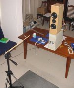
Just for the heck of it, here is a picture of my test environment yesterday ") not ideal but not to bad either. The pc under the speaker was purely for elevation. gave me a bit longer gate time, but unfortunately I couldn't quite push it far enough to get more resolution in speaker workshop.
not ideal but not to bad either. The pc under the speaker was purely for elevation. gave me a bit longer gate time, but unfortunately I couldn't quite push it far enough to get more resolution in speaker workshop.
The front baffle is very rough and was never originally intended to be used. It was more to sus out driver mountings. One thing I learned from my testing yesterday was that my idea of resessing the tweeter back into the baffle with rounded over edges was a really bad one!!!! huge trough in response between about 4.5 and 5.5K due to diffraction! (unfortunately I didn't save the response graph)
This is only a test box, final one will be different, but it has proven invaluable as a learning tool. Learn't quite a lot yesterday from my testing with the mic too.
Tony.
not ideal but not to bad either. The pc under the speaker was purely for elevation. gave me a bit longer gate time, but unfortunately I couldn't quite push it far enough to get more resolution in speaker workshop.The front baffle is very rough and was never originally intended to be used. It was more to sus out driver mountings. One thing I learned from my testing yesterday was that my idea of resessing the tweeter back into the baffle with rounded over edges was a really bad one!!!! huge trough in response between about 4.5 and 5.5K due to diffraction! (unfortunately I didn't save the response graph)
This is only a test box, final one will be different, but it has proven invaluable as a learning tool. Learn't quite a lot yesterday from my testing with the mic too.
Tony.
Attachments
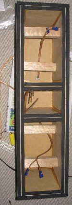
Ahhhh one important fact that I didn't mention. There is only one driver in that 6.6L the drivers have separate cavities.
Note I learn't something very usefull with my very dodgy braces that can be seen in this pic. The one directly behind the driver caused nast reflections, which caused a very nasty irregularity in the FR at about 700Hz! I'm now thinking that dowel may be a better thing to use as bracing!!!
The sealing foam is only for this test box, the final ones will be properly glued.
Tony.
the drivers have separate cavities.Note I learn't something very usefull with my very dodgy braces that can be seen in this pic. The one directly behind the driver caused nast reflections, which caused a very nasty irregularity in the FR at about 700Hz! I'm now thinking that dowel may be a better thing to use as bracing!!!
The sealing foam is only for this test box, the final ones will be properly glued.
Tony.
Attachments
I did the math, according to the formula below.
I used the following parmeters:
Vas = 19.8 liters, (for the two together)
Fs = 34 Hz
Qts = 0.41
I don't need to sim when I have the formula. In fact, the sim is based on Small's formula, which this is.
I used the following parmeters:
Vas = 19.8 liters, (for the two together)
Fs = 34 Hz
Qts = 0.41
I don't need to sim when I have the formula. In fact, the sim is based on Small's formula, which this is.
Attachments
wintermute said:Ahhhh one important fact that I didn't mention. There is only one driver in that 6.6L
Now you tell me, lol.
Let me recalc, back in a minute.
Doh, all the sims I did were for a single driver since I was modelling them in separate box volumes. I guess I should do one with two drivers and just double the volume.
Tony.
edit: just realised part of the problem, the drivers have quite different specs, I guess I should model based on the average specs of all the drivers and just double it. Actually I did do the average, that is how I came up with 6L (then added 10% as is the norm), what did I do with those average specs......
very strange. no matter what I do in unibox, I can't seem to make it give an f3 any lower than about 80Hz..... and I just realised that the only real effect of me putting in two drivers (provided the volume per driver doesn't change) is that the spl level will be higher.
I'm just having trouble working out why the model and the actual result seem so different. The impeadance curves are smooth, so I don't think I have any leaks..... Is it possible that the drivers behave differently to what the T/S params would suggest, or heaven forbid, my T/S measurements are completely wrong!!!
maybe time for me to try modeling in something else!!
Tony.
edit: just for the record, the average specs are below:
two drivers were each fairly similar, so I have grouped them in the box as being two most different.
Attachments
Using some screen measuring tools I have, (WinMeasure freeware), I get the F3 as being about 65 Hz, assuming your midpoint was +12.5. It might be lower, if that bump in the bass is an artifact of measuring nearfiled-Adire shows something similar. In that case, the F3 would be even lower-near the 56 Hz the formulas predict. Assuming that bump is not real.
What do you meassure as the Fc, impedance wise?
What do you meassure as the Fc, impedance wise?
Your measured specs all seem to be OK. The one with the highest Qts also has the lowest Vas, so in equal size boxes, it's Qts will be raises less than the others' Qts. So everything balances out, approximately.
I think you might be filling in something wrong in your unibox sim. You should not be getting predicted F3 of 80, or anywhere near it.
Unibox's predictions should be pretty close to the formulas I gave. And my predictions using those formulas are nowhere near 80 Hz.
I think you might be filling in something wrong in your unibox sim. You should not be getting predicted F3 of 80, or anywhere near it.
Unibox's predictions should be pretty close to the formulas I gave. And my predictions using those formulas are nowhere near 80 Hz.
All very weird.......
here is the impedance curve as measured yesterday (this is both drivers in the box. Interestingly the fb is pretty much what unibox predicts at 80Hz. Now looking at my chart (in weems book) if the Q is .7 (which it is kinda close to) then the fc should be 80Hz too.
I'm confused
Tony.
here is the impedance curve as measured yesterday (this is both drivers in the box. Interestingly the fb is pretty much what unibox predicts at 80Hz. Now looking at my chart (in weems book) if the Q is .7 (which it is kinda close to) then the fc should be 80Hz too.
I'm confused
Tony.
Attachments
I've been messing up.
In the other thread, kimbo said his Fs was listed as 29.5, but it came out 34 when measured.
Then you said your woofer measured 52, but should be 45.
I got the two confused.
I have been using 34 Hz as your Fs-which was kimbo's Fs, not yours.
Using an Fs=52 Hz, you do get an F3 around 80 Hz. The formulas say it, Unibox says it, and WinISD says it.
Sorry about that.
Yes, as I mentioned in a previous post, when Qtc = 0.7, then Fc = F3.
It was my mistake, confusing kimbo's woofer with yours.
But we still have the problem of the nearfield response.
Like I said, if you go the Adire site adn download their white paper on the Shiva, for a closed box Shiva they also have hump in the bass resonance which they tell you to ignore since it is an artifact of the nearfield technique.
Okay. Adire changed their white paper on the Shiva, that artifact is not on this more recent one as it was on the old one.
But it did show a bass hump near resonance that should not be there, and Adire said it was the result of the nearfield technique.
I think that is what is happening with your Speaker Workshop graph. That nearfield artifact is giving you false readings.
But it did show a bass hump near resonance that should not be there, and Adire said it was the result of the nearfield technique.
I think that is what is happening with your Speaker Workshop graph. That nearfield artifact is giving you false readings.
since this is a rantings thread
Just for anyone interested, below is the nearfield response that I measured when there was a 32mm square brace driectly behind the woofer (side to side) as in the pic earlier. Note the rather large spike compared to the other nearfield response I posted earlier.
I'll attach the impeadance curve on the next one. Very interesting to me that such a small object could cause such a big variation in the freq response! As I said earlier I learnt quite a bit from my testing yesterday.
Tony.
Attachments
- Status
- This old topic is closed. If you want to reopen this topic, contact a moderator using the "Report Post" button.
- Home
- Loudspeakers
- Multi-Way
- new morel MTM project: rantings