jam said:Ikoflexer,
Any news...................🙂
Jam
Ahm, yes, took a day off and went fishing. Caught a 8.5lbs carp, how about that 😀
Before that I've had some progress but my conclusions are not yet finished. Built a fresh v1, v2, and even a v1.5, all working. But they need to be assessed, to see if there is any real advantage in building something more complex and costly than v1.
Another variation?
I see you're the man for different cct idea!
I wonder if the input section of the Zen V.8 or 9 would make a rather good shunt cascode with the Lu power Jfet slaved to our familiar IRFP device - It's a very successful combination in these designs, and has sdded features in the F3, and "a pair of the cascode pair" (sorry!) is the heart of the DOA headamp!
I think there are still quite a few of the Lu1014D Power Jfets available from about $2.50 ea and don't really need to be matched for this sort of use.
The pcb for the V1 has been updated with the bigger caps, etc and hopefully, if it is okay, Salas will put it up soon.
pcb numbers and "things"
Thanks Salas,
Oh dear! I see some incorrect component numbers.
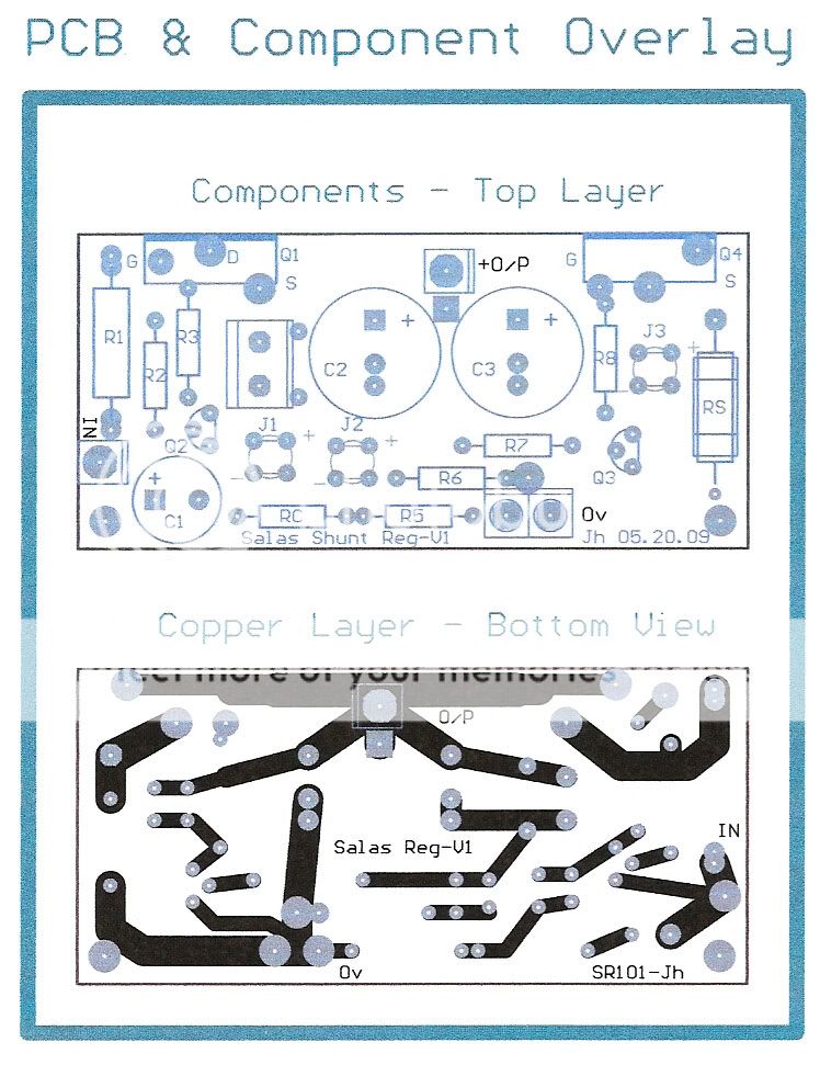
On the Blue Border ("PCB and Overlay") they're correct (Qs, Rs, Js, Cs)
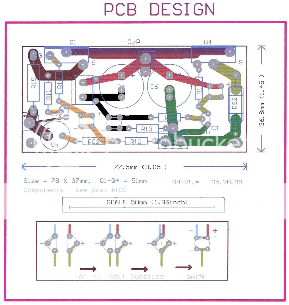
On the Crimson Border ("PCB Design") with the coloured tracks, they're all over the place, but it's pretty clear what they are.
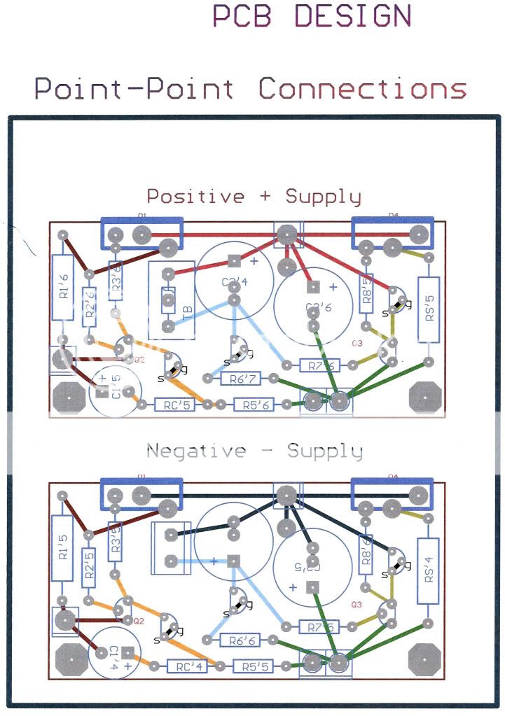
On the Black Border ("Point - Point") the numbers are the Protel sequencial ones and not correct, but again, it's fairly straight forward.
On the Negative diagram, the jfets need to be reversed as the gate/source aren't going to 0v here - sorry about that.
The point to point diagrams are set out as 1/10" to suit the standard "perf board" and you can easily copy off the diagram, adjust to the measurements of 78 x 37mm, and print out an overlay and stick it to the bare board - makes it easy, but correct that Jfet error first.
I hope this makes this simple, marvellous design easy to build, and that we all can benefit from the efforts of Salas, Ikoflexor and others - Thank You.
Thanks Salas,
Oh dear! I see some incorrect component numbers.
On the Blue Border ("PCB and Overlay") they're correct (Qs, Rs, Js, Cs)
On the Crimson Border ("PCB Design") with the coloured tracks, they're all over the place, but it's pretty clear what they are.
On the Black Border ("Point - Point") the numbers are the Protel sequencial ones and not correct, but again, it's fairly straight forward.
On the Negative diagram, the jfets need to be reversed as the gate/source aren't going to 0v here - sorry about that.
The point to point diagrams are set out as 1/10" to suit the standard "perf board" and you can easily copy off the diagram, adjust to the measurements of 78 x 37mm, and print out an overlay and stick it to the bare board - makes it easy, but correct that Jfet error first.
I hope this makes this simple, marvellous design easy to build, and that we all can benefit from the efforts of Salas, Ikoflexor and others - Thank You.
Thanks, will do later as there are probably other things that can be improved - early days yet.
I'll see about a few pcbs this weekend, and try it out in practice, rather than the usual P-P affairs!
On another subject, your B1 Circuit caught my eye - must do one for the lightspeed and compare to the present k170, j74 version - also, might have a look at this idea of adjusting the current to optomise for the sound - they're talking about it in the Jboz thread - interesting things.

test shunt ,Works !
HI Salas hot day here 27°
r1=15r rload 1k 5w
Iin 101ma Iout 44,8ma
Vin 57v Vout 44,8v
the Rload are very hot finger burn after 1sec Vout/Iout move slow up
the Q6 (mpsa) burn finger after 3/4 sec ?!
(no r6mod for now)
I see only now Moderator ....
HI Salas hot day here 27°
r1=15r rload 1k 5w
Iin 101ma Iout 44,8ma
Vin 57v Vout 44,8v
the Rload are very hot finger burn after 1sec Vout/Iout move slow up
the Q6 (mpsa) burn finger after 3/4 sec ?!
(no r6mod for now)
I see only now Moderator ....
Logical results. All seem OK.
Just make R5 100 Ohm (the one under Q6 of the ''ring of two'' MPSA CCS), because with 57V in and the now LEDs current, is running hot enough and its not good for its long term reliability.
P.S. For those who may wonder what ''ring of two'' we talk about, Nicoch has made a special double mono symmetric version of +/-45V Vout shunts for the driver stages of his EB class A amp kit. Because the voltages exceed 2SK170 max, he uses a ring of two MPSA05 60V 625mW NPN BJTs, to locally CCS his LEDs Vref part of main shunt CCS.
Attachments

ok Salas
as for test I dont use R on rail if I put 10R-C-10R-C I can lower to 55Vin, can be better (apart filter) for summer reliability??
as for test I dont use R on rail if I put 10R-C-10R-C I can lower to 55Vin, can be better (apart filter) for summer reliability??
You can lower down to 53V in (as it was on the original schematic), but the easier way is to make R5 75-100R so the CCS will work somehow lower. It does not change the LEDs noise behavior essentially. Maybe the 10R-C-10R-C will eat more than you expect. I have seen it doing so when there is a CCS to feed.
Hi Nicoch
When you finish please let us know what your listening impressions are.
I have a JLH class A amp that is under construction that could possibly benefit from this regulator.
When you finish please let us know what your listening impressions are.
I have a JLH class A amp that is under construction that could possibly benefit from this regulator.
with Salas shunt can only sound better 😉 if work well for x phono....
I will do next weekend but to much mod at the same time.....
-new psu dual mono (mur > stealth , panas 40kuf > nich. KG 80kuf) for pw stage
-ad separate trafo for driver plus new diode /caps plus Salas shunt
-lower the bias for summer
I will do next weekend but to much mod at the same time.....
-new psu dual mono (mur > stealth , panas 40kuf > nich. KG 80kuf) for pw stage
-ad separate trafo for driver plus new diode /caps plus Salas shunt
-lower the bias for summer
A small update with some observations. I found a bit of time to build all three variations, v1, v2, and v1.5. Driving the shunt mosfet with a darlington is v1.5. All three versions are built as air sculptures, so, in a way none of them benefit from a tight layout. But that does not seem to be a problem. So far they've all been tested only with a passive 470 ohm resistor as load, and also with the salas designed phono stage I have, drawing a pretty constant 50mA. For this type of relatively constant load there seems to be no significant advantage in using v2, or v1.5 over v1. The ripple on Vout was about 500 microvolts, but then I noticed something strange. The same exact ripple was on the GND as well. I checked very careful for ground loops but could find none. Then I checked my power line ground and sure enough, exactly the same size and pattern of ripple noise was on the ground. It seems that the noise I get through the power utility line ground is the only significant noise in my setup. I happened to have around a five section LC network, J.W. Miller, power mains AC filter, and when the regulator was plugged into this the noise was reduced to about 100 microvolts.
There are two lesson here for me. First, with a relatively constant load there is no point in building v2. This makes sense, since the most significant effect on the Vin ripple is due to M1, the series mosfet and it's related bias circuitry, and that part remained the same in v2. If there is no output ripple due to a varying load current, then the extra circuitry of v2 does not get much use. Second, all three versions work so well that the power utility noise becomes the significant noise source.
Next I would like to build some sort of varying load circuit to test the load regulation of each of these devices. If anyone has a recommendation, please let me know. Battery biased mosfet as the load, driven by a sine signal generator perhaps?
Edit: and if anyone has some experience with getting rid of noise interference on the mains ground please make suggestions.
- Status
- Not open for further replies.
- Home
- Amplifiers
- Power Supplies
- The simplistic Salas low voltage shunt regulator